This thread has been locked.

If you have a related question, please click the "Ask a related question" button in the top right corner. The newly created question will be automatically linked to this question.

THS4521: Output Impedance in Power Down mode

Part Number: THS4521
Other Parts Discussed in Thread: THS4551

Hello,

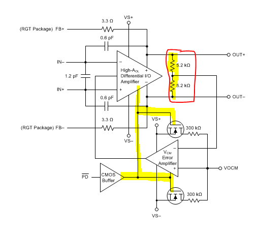
Could you please confirm the THS4521 output impedance when the chip in PD pin is driven low (power down mode). Is it high impedance? Would this chip be a good replacement for ADA4940-1 and be used to drive a differential communication line (capacitively coupled)? The common-mode input is 3.3V signal. The output is +/-2.5V differential signal.

Thanks 

  • The THS4551 was done to upgrade the THS4521 and match the ADA4940-1. 

    Power down shuts off the biasing circuit but the transistors and ESD diodes are still there.- I do believe there is an active hold off on the outputs. 

  • Thanks Mike. I could use THS4551 . First, could you please confirm what is the impedance I should expect when THS4551 is in PD mode?  ADA4940-1 will be in high impedance when DIS Pin is low. Any issue with using THS4551 as a 50-ohm line driver? 

    The block diagram shows that the transistors are not connected to the Diff. Output. The PD seems to force the internal Op-Amp into power down. The output impedance is close to 10K-ohm? 


    Regards.  

  • Well yes, at a small signal you will see those CM sense R's, but more thoroughly if you are driving a signal back into the output you will find diodes and other nonlinear loads. 

  • And of course WB you will see the external R's still there when the device is shut down, that gives you both a forward and reverse signal path around the device. I meant to be clearer - the diodes that are on the output pins are the ESD steering diodes to the supplies - Also, I meant to say I don't think there is any active hold on the outputs when disabled, some parts do have that but not these FDA's I don't think. 

  • Hi Mike. 

    You have indicated in your first statement yesterday that "I do believe there is an active hold off on the outputs". In your last reply you said "I don't think there is any active hold when the device is disabled". The simulation model for these FDA's doesn't include the behavior of disable signal. I need a definite answer as it's risky to release a design without bench testing the chip to verify the output status and characteristic impedance. As for ADA4940-1, it does have high-impedance when the /DIS signal is driven low.

    Thanks for your feedback. I think we can close this thread.  

  • The ADA4940 opens up the path to those output pin CM sense resistors in disable? I would find that surprising. The original THS4551 TINA model tried to include the shutdown feature, attached. However, everything that feature does at a macromodel level is really hard to model - and I doubt the ADI model does much better. Even the designer files are sketchy on shutdown as off transistors are not a modeling focus. 

    FDA_THS4551 2016 model.TSC

  • Here is where you are reading this, we showed a more detailed internal block diagram than they do, but those output sense resistors are definitely in the ADA4940 also or it wouldn't work as an FDA. We did add switches in series with the supply divider setting up the midpoint default bias voltage - those open on shutdown to reduce off current dissipation. And, just like they say here, the feedback networks back to the inputs are still there in shutdown and the THS4551 also has protection diodes internally across the inputs that might turn on if a large signal came into those nodes in shutdown. 

    Yes, those output resistors are there - just no value - and they are not showing the default mid supply setup that has to be there as well into the Vocm control pin. 

  • Thanks Mike. I am ordering the EVAL board to THS4551 to get some empirical data. I will let you know how it goes.

  • Would be interesting, we never really pursued why you are interested - several possibilities, forward path isolation would be a tough one as the external R's are still there. I assume you are also getting the ADA4940 to try as well, they really can't be high impedance in shutdown as those CM resistors have to be there, and they can't be too large for noise and CM loop bandwidth reasons.