This thread has been locked.

If you have a related question, please click the "Ask a related question" button in the top right corner. The newly created question will be automatically linked to this question.

INA226: not response

Part Number: INA226
Other Parts Discussed in Thread: TMP422

Hi team,

My customer uses INA226 in their project, now they meet a issue, could you please help to give some comments and suggestions? 

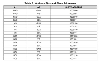
The customer connect A1 and A0 to GND when using INA226, according to Table 2, at this time the device address is 100_0000.

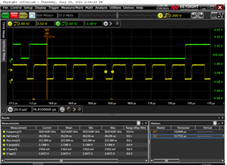
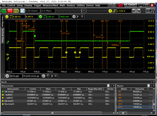
But when they test, they found the INA226 is not responding. They checked that the SDA corresponding to the ninth clock is H. The timing of the tests did not reveal a problem, as shown in attachment time4. Other test images such as time5 and Time6. So they would like to ask what are the reasons for the INA226 not responding?

Thanks for your support!

Regards,

Ivy


time4

time5

time6

  • Hi team,

    I would like to confirm one more question, as stated in the datasheet of INA226, that too large a dv/dt can trigger ESD protection for the device, so it is recommended to add RC filter to the circuit.

    If ESD protection is triggered for a device, will it affect the device's I2C interface communication?

    Thank you!

    Regards,

    Ivy

  • Hi Ivy,

    Triggering the ESD protection generally should not affect the I2C interface communication. Of course if such event is catastrophic to the extent that the device is permanently damaged, then all bets are off.

    Regarding the original question of device not responding – a likely cause is data hold time violation (thank you for the well-illustrated screen shots BTW). I don’t see hold time measurements, and to the naked eyes, the falling edges are overlapping. If this is the case, you could move SDA by more than 10ns after that of SCL. The issue should go away. The hold time requirement applies to all bits not just the circled.

    Regards, Guang

  • Hi Guang,

    Thanks a lot for your reply and support!

    The following is the test image of the hold time, tHDDAT=722ns, which meets the specification's 10-900ns timing specification, but slave has never responded. After replacing the IC, there is still no response, as shown in figures 1 and 2.

    When the customer designs the circuit, the signal from the sense resistor is directly connected to the IN+ and IN-, VBus signals from the INA226  connect to the IN+, and the IN+ and IN- without RC filtering circuits are designed. Does this affect the communication of the I2C interface? Please help to give comments, thank you for your support!


    Regards,

    Ivy

    Figure 1

    Figure 2

    Figure 3

  • Hi Ivy,

    Like I mentioned previously, input filtering does not affect communication of the I2C interface.

    Did customer check pin connection and voltages, including supply and ground? Another question to ask is if other I2C devices are working properly. We can also look at customer’s schematic.

    Regards, Guang

  • Hi Guang,

    Thanks for your support.

    Below is the schematic. Could you please help to review?

    Both R3250 and R3251 are replaced with 0 Ω resistors. Current flows from +12V_IN through a 5mΩ resistor to power the board.

    On the same I2C bus, other devices function normally, such as the TMP422, which reads the temperature value normally.

    Thank you.

    Regards,

    Ivy

  • Hi Ivy,

    Thank you for the additional information. Can customer monitor VS pin to see if a stable 3.3V is present while communication is on-going?

    Regards, Guang