This thread has been locked.

If you have a related question, please click the "Ask a related question" button in the top right corner. The newly created question will be automatically linked to this question.

LMV324 : Clipping output signal in one channel, causes distortion in other channels too

Other Parts Discussed in Thread: LMV324, TLV274

Hi,

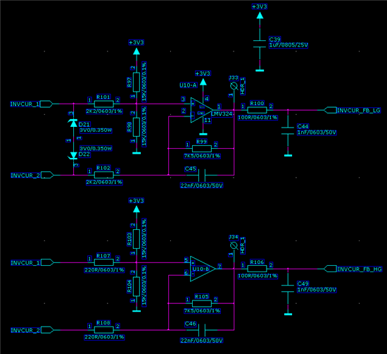
I am currently doing a design where a TMS320C28034 based control board needs to measure mains currents up to 16Amps. I have a 50/60Hz current transformer secondary terminated by a 5R6 resistor and connected to two differential amplifiers (both a packaged on the same LMV324 die) supplied by 3V3. The current transformer signal is offset by 1.65V at each opamp input. One amplifier has a gain of 4.2, while the other has a gain of 34. The purpose of the higher gain amplifier is to measure small AC currents more precisely. This amplifier will start clipping with mains currents from 1.5Amps and up. However, this does not matter since at 1Amps and up, the software automatically selects the lower gain (4.2) channel for current measurement.

The problem that I am experiencing is, that when I am probing the lower gain channel, a distortion in the output sinewave appears as soon as the higher gain channel start clipping.

What is causing this? Is there a cross talk issue on the opamp die? Is the clipping higher gain amplifier injecting distortion signals into the lower gain inputs?

I have set the gains already with relativily low resistor values (7k5/1k8 for the lower gain channel and 7k5/220R for the higher gain channel) in order to make it less immune agains interference.

Any help is greatly appreciated!

Thanks,


Daniel...

  • Hello Daniel,

    Assuming that each differential amp is a single channel of the LMV324 and the remaining 2 channels are used for some other purpose, I will answer your question.

    The diff amp will be a load on the current transformer. This load will be linear until one diff amp starts to clip. At this point the load (on the inverting input) changes to different value. This change in loading will distort the input signal and show up on the other amplifier. This distortion can be greatly reduced by increasing the resistors on the high gain amplifier by 100 times. You could also use one of the free channels to buffer the input before it goes to the high gain amp.

    Better yet is to change the diff amps to non inverting amps. This will prevent the distortion provided that the 1.65V reference is solid.
    See attachment for schematic. Ignore the op-amp device name..  Gain=(7k5/1k8)+1


    Regards,
    Ron Michallick


  • Hello Ron,

    Thanks a lot for your reply. I will try your suggestions, but have a few questions left :

    1. Will this behaviour be the same when I replace the LMV324 with a TLV274?

    2. Please see below the current schematic. The 5R6 burden resistor of the CT is connected between the input ports 'INVCUR_1' and 'INVCUR_2' . As you can see, we are using 15k/0.1% precision resistors in order to have very small errors on the 1.65V offset. In your proposed schematic with the non inverting amplifier, how can I implement a solid 1.65V reference with resistors only? I do have one channel on the LMV324 left which could act as a reference buffer I think. 

    3. Given the above schematic, how should I implement the left over LMV324 amp when I would like to use it as a buffer in front of the high gain amp.

    I am sorry for all the questions, I just wish to have as much options as possible to choose from in order to fix this distortion issue.

    Thank you very much!

    Daniel...

  • Daniel,

    Monday I will do some bench testing to verify that the LMV324 is not the source of the cross talk.
    In the meantime, can you post or desribe the distortion you see?
    Also useful is looking at the input signal, INVCUR_1&2 to see if the distortion is also present there.

    Regards,
    Ron Michallick


  • Hello Ron,

    Please see below two images. The first image shows the high gain amp output (yellow), the low gain amp output (blue) and the raw INVCUR_1/2 input (green), prior to any clipping at 1Amp mains current :

    The second image shows the same signal, but now with the high gain amp clipping severly (as intented) at a mains current of 6Amp. I have made a big step from 1 to 6Amps in order to see the distortion on the low gain amp output more clearly. As you can see, the distortion appears in the rising edges of the sinewave, while the current transformer output signal remains untouched :


    I seem to have not yet mentioned that a third amp channel on the same die, which amplifies a signal coming from a second current transformer, does not show any distortion on it's output with high gain channel 1 is clipping.

    I hope this helps. Your input is appreciated...

    Daniel...

  • Daniel,

    Thank you for the schematic and waveforms. They are very helpful. Your design is sound; I do not see the cause of the distortion in the schematic.
    I also no longer believe the cause is a loading imbalance during clipping.

    I have tested interaction between amps 1 and 2 in the lab and the result was negative. No interaction was observed.

    Have your observed this effect on more than one unit or board?
    I do not have a good theory at this time.

    Regards,
    Ron Michallick


  • Hello Ron,

    Thanks for your evaluation. As this effect was observed on our first and only prototype board, I don't have any more units that I can check on this behaviour. I will do some additional measurements and tweaks (also like to replace the LMV324 for a TLV274) to see if I can find the source of this problem.

    Regards,

    Daniel...


  • Hello Ron,

    The problem seems to be solved. I have increase the resistor values around the high gain amp by a factor of 10. So the input resistors are now 2k2, the offset divider resistors are 150k and the feedback resistor 75k. The distortion on the low gain amp output that appeared once the high gain amp starts clipping, has now disappeared.

    I did not dare to increase the high gain amp resistors by a factor of 100 as you suggested, since I suspect that the offset divider resistors would become too high and make the 1.65V offset too weak. Especially in combination with an LMV324 (input bias current issues). What do you think?

    Thanks.

    Regards,

    Daniel...

  • Daniel,

    I'm glad to hear that it only took a 10X increase to clean up the signal.  Perhaps my initial diagnosis was the correct one.
    The bias current sees the parallel resistance of input resistor and feedback (or 1.65V bias) so IIB should not be a problem.
    There is no need to increase all the way to 100X.

    Regards,
    Ron Michallick


  • Thank you Ron.

    We can go ahead now and hope to finish the design soon for production.

    Regards,

    Daniel...