A related question is a question created from another question. When the related question is created, it will be automatically linked to the original question.
If you have a related question, please click the "Ask a related question" button in the top right corner. The newly created question will be automatically linked to this question.
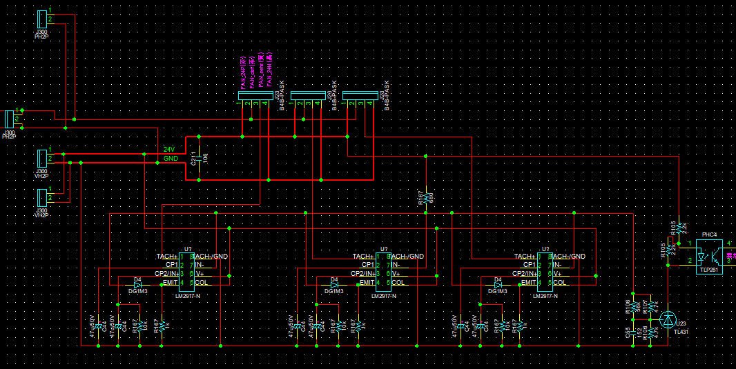
I have not seen an application before where three LM2917-N emitter outputs are being OR'd together. More information is needed to make that determination what may ne happening in the circuit.
Please explain what you mean by ". . . does not work well."
Have you seen the LM2917-N applied in this manner before? If so, can you provide the resource that explains the application concept?
Since the R and C values used with each of the three LM2917-N are the same are they intended to produce the same output voltage for the same input frequency. Is that correct?
If the three LM2917-N are intended to produce the same output voltage why are three being applied? Is it a matter of output current drive?
It looks like the output transistor emitter of each LM2917-N has a 1 k resistor to ground, but then each has a pull-up to the +24 V supply through the D4 at each output emitter and then the common 680 Ohm resistor. The current through the 680 Ohm resistor and each D4 diode would have to be sunk by each of the 1 k resistors and a voltage drop would be developed across them as they sink the current. This raises the voltage at each LM2917-N output emitter. What is the intention of the pull-up?
The IN- (pin 7) of each LM2917-N output op amp connect back to their individual output emitter via the D4 diode, but then all three IN- pins are all connected together. Each op amp will have its own unique voltage offset and tying their summing nodes (IN-) together would result in slightly different output voltages. OR-ing three different output voltages will result in each output transistor sourcing somewhat different output current.
I'm sorry if it is rude or inappropriate to you, since I use the online translation site.

The purpose is a circuit that detects the lowest level among multiple fan speeds. You don't have to know which fan you are.

1.The fan sensor has been damaged.
2.There is none.
3.I think it is good because it is a diode or circuit for detecting low voltage.
4.This is a problem with the board configuration.
5.I am thinking of detecting the level of f-v conversion voltage.
6.It is based on the Select-High Circuit in the data sheet.
No problems, I was just asking questions so that I can better understand your application circuit. Thank you for providing answers to my questions.
You mention in number 1 item, "The fan sensor has been damaged." Did the circuit worked as expected up to that time, but then while operating the fan sensor later became damaged? Or did it not function at all and the fan sensor became damaged?
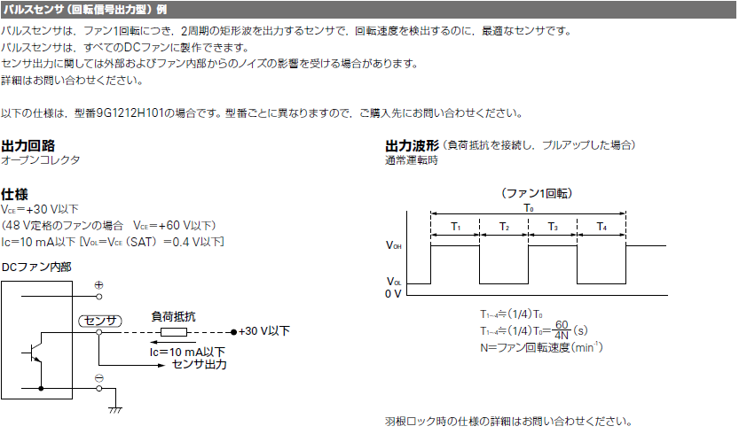
I need to know something more about the fan sensor that provides the LM2917-N input. What kind of sensor is it?
The reason I ask is because the LM2907-N and LM2917-N in the 8-pin package has pin 8 internally grounded. Pin 8 is the inverting input of the input comparator. The other input, the non-inverting signal input, must see a signal that passes through 0 V and goes negative by a few tens or hundreds of millivolts for a period, in order for the input comparator to change state. Therefore, if the fan sensor does not produce an output voltage that has some portion of its waveform crossing through 0 V and becoming negative for a period of time the LM2917-N will not initiate the F-to-V conversion.
If this is an issue for your circuit, FIGURE 5, in Tachometer Input Configurations in TI/National Application Note AN-162, "LM2907 Tachometer/Speed Switch Building Block Applications," explains how to develop a small negative-going input waveform such that the F-to-V conversion commences. Here's a link to AN-162:
I felt that the constant and the circuit were wrong, and as a result of correcting the constant and assembling it like the sample circuit, it worked normally.
The difference from the sample circuit is that you have to insert a resistor between pin 1 and the sensor.(.bmp)

Is it possible to create a 3-parallel detection circuit by applying the circuit shown in Figure 39?
You mention "as a result of correcting the constant and assembling it like the sample circuit, it worked normally." Does this mean you are able to obtain the expected response from the fan sensor using this circuit?
Is it possible to create a 3-parallel detection circuit by applying the circuit shown in Figure 39?
When I review Figure 39 I now see that it looks much like the three LM2917-N circuit you proposed except it has separate inputs from two different sources; two auto wheels. The Application Note AN-162 that I referenced previously provides an explanation of how this circuit functions on Page 15, Anti-skid functions, an automotive application. It states:
"One of the questions which the systems designer must answer is whether to use the average from each of the two wheels on a given axle or to use the lower of the two speeds or to use the higher of the two speeds. Each of the three functions can be generated by a single pair of LM2907-8 as illustrated in Figures 26 – 28. In Figure 26 the input frequency from each wheel sensor is converted to a voltage in the normal manner. The op amp/comparator is connected with negative feedback with a diode in the loop so that the amplifier can only pull down on the load and not pull up. In this way, the outputs from the two devices can be joined together and the output will be the lower of the two input speeds."
Your application using three LM2907-N F-to-V converters has there individual Tach inputs connected together. Would you be changing the circuit so that they are separated and each input goes to a different fan sensor?


 Is it possible to create a 3-parallel detection circuit by applying the circuit shown in Figure 39?