This thread has been locked.

If you have a related question, please click the "Ask a related question" button in the top right corner. The newly created question will be automatically linked to this question.

INA281-Q1: Vout

Part Number: INA281-Q1
Other Parts Discussed in Thread: INA281

Hi team,

My customer evaluated INA281A2QDBVRQ1 in their project, and met some issues now. Could you please kindly help to give some suggestions?

Refer the datasheet, INA281A2QDBVRQ1 can normally work as long as  the output voltage is below VCC-0.3.

But they found the IC won't work properly when it output 2V at high temperature(105°C).

Then at the normal temperature, the IC can work well.

The VCC is 3.3V. Rs is 0.002ohm.

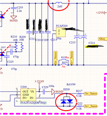
Below is the test result and schematic.

Thanks for your help.

Regards,

Ivy

The blue curve is output voltage, green curve is output current.

  • Hi Ivy,

    Have you tried to disconnect the INA281 output pin from the circuitry it is driving, as well as remove the input clamp to see if any of these helps?

    Regards, Guang

  • Hi Guang,

    The customer tried to remove input clamp, the problem is improved, but it could not be completely resolved.

    The INA281 is used for feedback sampling, so the output cannot be disconnected, otherwise the actual circuit state is not simulated well.

    The customer also tried to reduce the RS to 1.5V output of the  INA28, and the INA281 can work well.

    Could your please help give some suggestions?

    Regards,

    IVy

  • Hi Ivy,

    Thank you for the additional information. It is possible that removing the clamps improved loop bandwidth. Besides, initially INA281 output might be clipped occasionally at the first few pulses after load current suddenly changes, effectively further limiting the loop speed. If this is the case, reducing the max output level should help.

    In any case it doesn’t look like a device or circuit problem and I’m glad a solution was identified.

    If you want to verify further, it may be possible to break the loop (at the input for example) and provide an artificial input voltage to see if the original oscillation problem goes away. If it does, then the loop bandwidth theory is probably correct.

    Regards, Guang