Other Parts Discussed in Thread: TINA-TI
Hi Team,
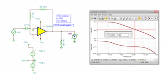
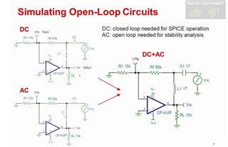
I want to get loop gain Bode by TINA-TI. The precision lab video taught the non-inverting amplifier circuit like this picture.
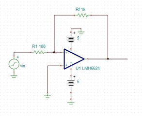
But I can't figure out how to build the circuit to simulate inverting amplifier circuit like this
I would like to know how to break the point and change the signal position to get the Open-loop module. And where to measure feedback value(like Vfb in the first picture)?
Thank you. Best regard.