Part Number: OPA657
Hi,
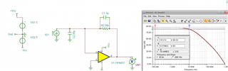
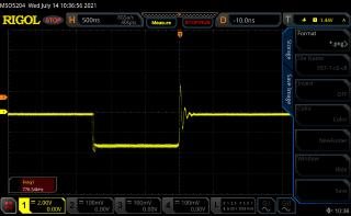
We use OPA657 circuit as TIA amplifier. Our output signal is on the following output.
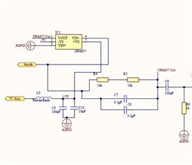
Our circuit is on the following picture
How can we prevent sinusoidal responses on digital pulse?
Part Number: OPA657
Hi,
We use OPA657 circuit as TIA amplifier. Our output signal is on the following output.
Our circuit is on the following picture
How can we prevent sinusoidal responses on digital pulse?