This thread has been locked.

If you have a related question, please click the "Ask a related question" button in the top right corner. The newly created question will be automatically linked to this question.

LM741: Very high impedance (over 100 Meg Ohm) circuit design

Part Number: LM741
Other Parts Discussed in Thread: TLV9001, LM358

Hello all,

I am currently working on the dynamic photoresistor which has a resistance ranging from 1 MEG - 300 MEG ohm. And I want to indirectly measure light intensity using the analog output..
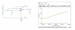
I composed the circuit using the TINA and R4 is the dynamic photoresistor. In the simulation, it seems to work. However, in the breadboard simulation, I cannot read out signal correctly. And from the ESP32 or Arduino MCU boards, the analog signal was floating. So I tested very simple two serial 10 MEG ohm resistors testing.

a---- R1 (10 MEG) ---b--- R2 (10 MEG) ----c

Vac = 5V. However, Vab = 1.63 V, Vbc = 1.63 V which means that Vac not equal to Vab + Vbc. (I used multimeter).

Accordingly, my guess is that very low current due to high impedance can cause incorrect signal reading from MCUs and even multimeter.

Is there any circuit design or an electrical component that can solve this issue?

I have worked on this for a long time, however, I couldn't still fix it and feel little bit desperate.

Any kind of suggestions can be helpful and I am willing to try!

Thanks

Best

Seungjun

  • Hi Seungjin,

    two mistakes:

    1. The LM741 needs a minimum supply voltage of +/-10V according to datasheet.

    2. Input bias current of up to 500nA results in a voltage drop across R1 of

    500nA x 22MOhm = 11V Thinking

    I would take the TLV9001 for this task.

    Kai

  • Thank you for the comment Kai,

    I just considered maximum input voltage +/- 22. Thank you for the comment. I have one additional question. Regarding the V+ and V-, can I supply with V+ (i.e., 5V) and GND? Or it always needs to be +5V and -5V supplied to the OP-AMP? TLV9001 also has +V and -V input pins.

    And about the second comment, I was just sharing my multimeter measurement results with below circuit.

    5V -----"Node A"----- R1 (10 MEG) ----"Node B"----- R2 (10 MEG) ----"Node C"----- GND

    Just very simple two resistors circuit with 5V applied voltage. And Vab (1.63) + Vbc (1.63) =/ Vac (5V). I think this is because current level is lower than minimum input current for the multimeter.

  • Hi Seungjun,

    In addition to Kai's comments I would recommend removing the capacitor directly on the output of the amplifier. This will not provide any filtering without a resistor is series and will only cause stability issues. Please see our TI Precision Lab Videos on Stability for more information.

    Thank you,

    Tim Claycomb

  • Then, currently TLV9001 is all sold-out. Do you have any other suggestions? I also have LM358 in my hand and I am wondering if this can solve the issue.

    And also, you don't think that I need to add any additional component to amplify the current level, right?

    I am still worrying about the very low current.

  • Tim,

    Thank you so much for the comment. You are talking about the C2 capacitor, right?

    I will also test that. By the way, is there any diagnostics on why I cannot read out the analog signal correctly from the Arduino or ESP32? I keep thinking it is because of the low current. But I am not 100% sure. And if that's the case, how can I solve this issue?

  • Hi SJ, 

    Yes, C2 should be removed.

    1. Did you make sure that there is 5V coming from the MCU? That would be the first step. 

    2. Try testing without the amplifier connected to the voltage divider. Not having the op amp above the minimum supply may cause an issue and the LM741 has very high input bias current as Kai mentioned. If you remove R5 in your circuit, you will remove the op amp from the voltage divider. If after removing R5 you still can't read the correct voltage, I would think there is something else causing issues.

    Thank you,

    Tim Claycomb