This thread has been locked.

If you have a related question, please click the "Ask a related question" button in the top right corner. The newly created question will be automatically linked to this question.

LMH5401: Need DC offset drift information

Part Number: LMH5401
Other Parts Discussed in Thread: LMH6401

Team-

Supporting a wide-band signal chain application with the LMH5401 in the front end.  It needs to be DC accurate; the ADC has some internal offset correction capabilities, but not sure if it is enough to cover the contribution of the LMH5401 and if additional temperature compensation is required.

The data sheet specifies the input offset voltage (+/-5 mV,max), but doesn't appear to spec offset drift.

Figure 54 has a graph of differential DC offset voltage vs. temperature, but not sure if we can rely on this without more substantial statistics.

We are concerned with operating from 0-60C, which appears to be pretty flat temp co.

Any other comments or data you can provide on this topic would be appreciated.

-Steve

  • Hello Steve,

      LMH5401 is a bipolar input which will have the lowest offset voltage and temperature drift out of the amplifier inputs. You are correct Figure 54 will give you the information on offset voltage drift. This parameter will be within 1-10uV per Celsius degree (which looks very flat in the mV range which are the units in the plot). I am looking into if we have more data for this spec, and will get back to your shortly.

       Would you be able to share the ADC which this device will be interfacing?

    Thank you,

    Sima 

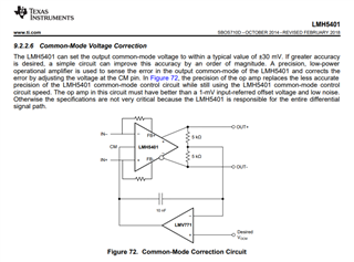
  • The LMH5401 was primarlly focused on very low HD through higher F. Not only are the DC errors poorly specified for the differential path, but the output CM offset and drift is poor and not specified. This little servo loop circuit was added at the 11th hour to give an easy option to improve CM control - very sparce info, I normally use this at the end of an interstage filter to the ADC with CM pickoff at the final ADC input. Keep in mind a lot of ADC's have a sample rate dependent input CM current that will give a DC level shift from the FDA output CM to the ADC input CM if there is an IR drop towards the ADC - as in a C iso R or interstage filter design. 

  • Thanks Michael; good to hear from you again.  This application has (so far) an LMH6401 PGA after the '5401 and the CM is reset by that device.  This signal chain must be accurate down to DC and just want to get as much evidence as possible regarding drift- I think we're OK, but need to make sure we don't need to add additional offseting calibration in the front end.  (there is some in the ADC back end, but it is a little limited especially once you put gain in front of it)

  • Hello Steve,

      Sorry for the delay on this. I have sent you an email on the information I could find on offset voltage and drift for the LMH5401. For a cascaded LMH5401 and LMH6401 design, we do have collateral on this which I have linked here.

    Thank you,
    Sima