This thread has been locked.

If you have a related question, please click the "Ask a related question" button in the top right corner. The newly created question will be automatically linked to this question.

INA250: PA quiescent current sense

Part Number: INA250
Other Parts Discussed in Thread: INA190

Wondering if the INA250 would be a good choice for an application of measuring the quiescent current (Idq) draw of an LDMOS PA.  

Would prefer a device with an integrated resistor, but could use something like the INA190 if more appropriate for my application.

Current Sense Amp. Requirements

Current Sense Placement: High-Side

Common Mode Voltage: 28V

Current Range measured: 20mA – 200mA

Accuracy: 0.5mA

Current measurement direction: uni-directional

Sensor output: Fed back to AUX ADC (Is placement distance from sensor output to ADC critical?  Distance in this case could be up to 100mm or more)

12-Bit Aux ADC input range: 0 - 3.3V

I noticed that when I put in the parameters into the Current sense amplifier error analysis INA250https://www.ti.com/product/INA250?dcmp=dsproject&hqs=pf

The Total Error % is > 100% for much of the Sensed Range

Sensed Current range: 0.02 - 0.20 A

Supply Voltage: 4.5V

Common-Mode voltage 28V

Also for the INA250, or if another part is recommended, which Gain version of the part would be recommended for feeding a 12-bit ADC with a input range of 0 - 3.3V?

Thanks,

Mike

  • Mike,

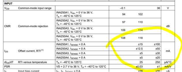
    The error the calculator showed you is most likely accurate, and unfortunately I don't think the INA250 is going to be a good fit here, due to the size of the currents you are looking to measure on the lower end of the range. Similar to any op amp, current sense amplifiers have an offset, and for this type of device, we refer that offset to the input as a current. As shown in the INA250 datasheet:

    This shows that for even the A4 variant, the offset current here is 20mA, which is equal to the current you wish to measure. This means that there would be 100% error in the measurement from the offset current alone (for worst case), before taking any other error sources into consideration. 

    If the bandwidth is sufficient, the INA190 will probably be a good candidate here, as it has a capacitively coupled input, which is ideal for measuring small currents.

    When determining gain for the ADC inputs, don't forget that the gain choice is only one tool at your disposal, as you may also choose the shunt in tandem with the gain to determine the output voltage of the amplifier you ultimately choose (VOUT = I_SENSE*R_SHUNT*GAIN). The tradeoffs here are that as you choose a larger shunt, you increase the accuracy of the signal at the lower end of measurement (raising it away from the offset voltage), but do so at the expense of heat created in the shunt. As you increase the GAIN, you loosen the restrictions on the shunt, but do so at the cost of decreased BW.  

    Regarding the spacing from the output to the ADC, I don't think this will be an issue, but be aware that long traces may subject to noise and will also add resistance between the output pin and the ADC input. You may consider placing a buffer at the inputs of the ADC if necessary.