Lab DC power supply, semiconductor testing and battery testing require accurate constant-current and constant-voltage output DC power supplies. The current and voltage control accuracy of the equipment need to be better than ±0.02% of the full-scale range over a ±5°C ambient temperature change. The power supply includes an output stage, current- and voltage-sensing circuits, control loops, an analog-to-digital converter (ADC) and a digital-to-analog converter (DAC), shown in the figure 1. In the post, I will focus on current sensing stage that needs to be low-drift and low-noise. To read more, refer to the technical article How to design an accurate dc power supply.

Figure 1: Typical block diagram of a DC source
The accuracy largely depends on temperature drift of the current-sense resistor and amplifiers. The amplifier’s input offset error and gain error are not a concern, as both errors are adjusted during system calibration. The amplifier’s offset and gain drift, output noise, and gain nonlinearity are difficult to calibrate, however, and you should consider these errors when selecting a current-sense amplifier.
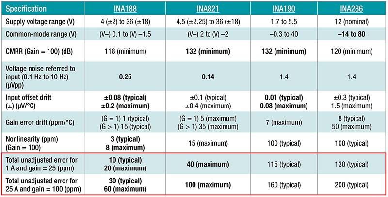
Using equation, you can calculate the total unadjusted error of the current-sense amplifiers shown in Table 1. The error from the common-noise rejection ratio is relatively small, and you can ignore it.

The INA188 has the least error among the amplifiers listed in the table. The error calculations use a ±5°C temperature variation, with 100-mΩ and 1-mΩ current resistors chosen for 1-A and 25-A outputs, respectively. Error due to gain drift is not included in the total error estimate. It will be small fraction of Gain drift x ΔT error at low current output (<5% of full-scale) where accuracy is most important.

Table 1: Total unadjusted error of current-sensing amplifiers
Additional resources
- Check out the Precision Amplifiers Battery Test Systems video series.
- The Digitally Controlled Non-Isolated DC/DC Buck Converter Reference Design provides an example of buck converter implementation.
- Read the technical article, “How to Design One Battery Tester for a Wide Range of Sizes, Voltages and Form Factors” to understand the benefits of digital control loops.
- For test data, see the Battery Tester Reference Design for High Current Applications.

