This thread has been locked.

If you have a related question, please click the "Ask a related question" button in the top right corner. The newly created question will be automatically linked to this question.

OPA627: OPA627BP

Part Number: OPA627

Dear Support,

KIndly help me on the part number OPA627BP (DC:1931+,   COO: Malaysia)

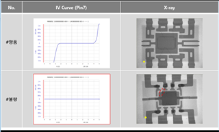
Based on X ray, found wire bonding and lead frame design is different. Kindly help to check and confirm if this is valid and normal.

Please refer to photo for reference. Thanks.

  • HI Isagani,

    We are not at liberty to openly release this kind of information because product counterfeiters can use it to their advantage. I have contacted our Precision Amplifiers Customer Quality Engineer to find out what information if any, we would be able to provide.

    Regards, Thomas

    Precision Amplifiers Applications Engineering

  • HI Isagani,

    Adding to Thom's reply. Do these parts purchase from TI authorized distributor or TI Webstore? If it does, you may be able to return the "questionable" part to the authorized distributor for further investigation. Otherwise, there will little or no traceability in these parts. 

    Best,

    Raymond

  • Hi Isagani,

    I have never X-rayed an OPAmp before using it in a circuit in my whole carreer. Why would an development engineer be interested in the X-ray photo of a OPAmp?? Or are you a surgeon and want to carry out a cardiac catheter examination of the OPA627 or cure a broken leg?

    Kai

  • Pretty funny Kai, 

    Very normal to xray devices coming out of a board that does not pass testing - and, not uncommon to find it is not a valid part being sold at a discount by pirate disti's. 

  • Hi Isagani,

    I have been in contact with our Customer Quality Engineer and he conformed that we are not able to provide any confirmation regarding this OPA627BP material. 

    I may be able to lend some help wit the curve trace images you provided for the two different OPA627BP devices. The OPA627BP was fabricated on a bipolar transistor process that accommodated the JFET input transistors. If the curve trace for the upper device was made pins pins 7 (V+) and 4 (V-) you would expect to see conduction in the reverse direction due to forward biasing the substrate diode, and then in the forward direction when the op amp begins to enter the power up region. This likely indicates an active op amp, but tells you nothing more about it.

    The second and lower curve trace, if swept across the same pins, shows no conduction in either direction. That would indicate an open circuit where we would expect to see a similar curve to that seen in the first curve trace. That looks suspicious.

    Regards, Thomas

    Precision Amplifiers Applications Engineering