This thread has been locked.

If you have a related question, please click the "Ask a related question" button in the top right corner. The newly created question will be automatically linked to this question.

OPA333: Howland Source - Stability

Part Number: OPA333

Hello,

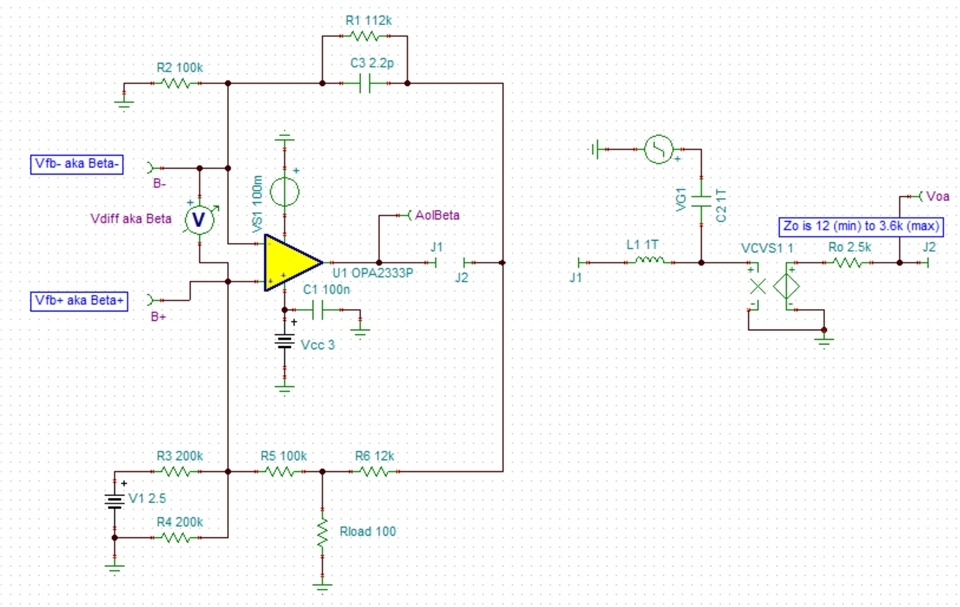
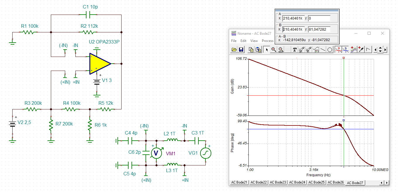
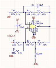
I've been using an OPA333 as a low-power, low frequency Howland Current Source - generally it works quite well but I'm finding a small amount of oscillation creeping in at an ADC further down the processing chain so I'd like to do some stability analysis on this current source as I have reason to be suspicious that this might be the source. Schematic of relevant section is below:

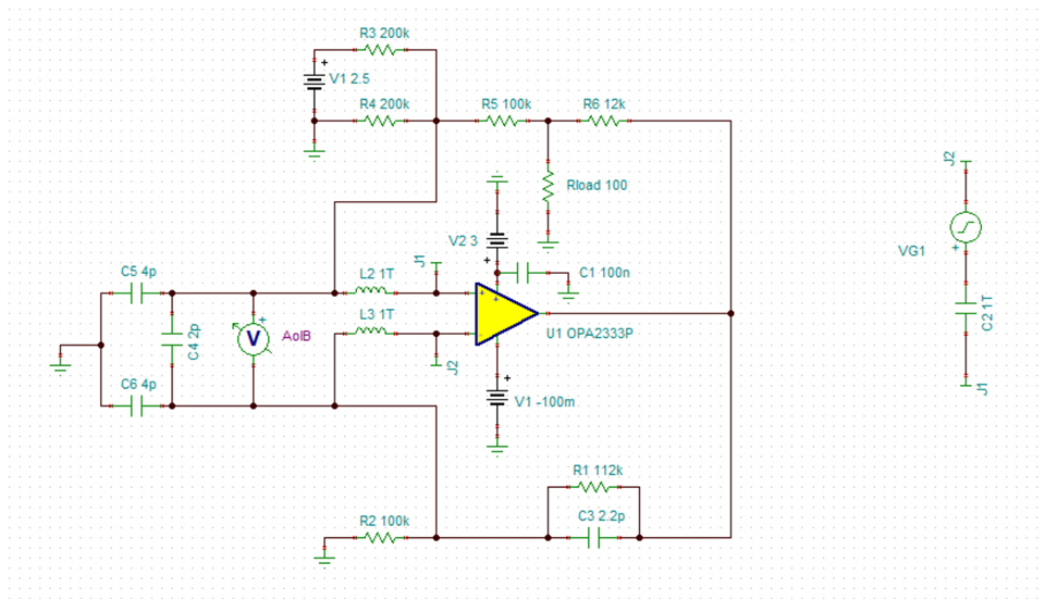
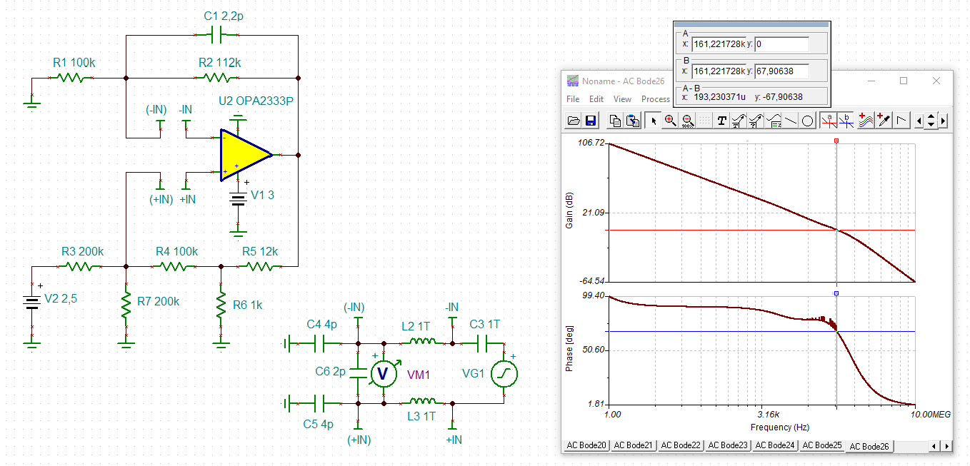
I've used Collin Wells' material on stability a few times in the past and found it very useful, particularly the sections on how to break feedback loops in TINA Spice simulator to see how it looks in open-loop. However, this time I'm not quite sure where to start, as there are both positive and negative feedback loops. Any suggestions on what I can do here?

Thanks,

Gordon.

  • Hi Gordon,

    what is your load (resistance, capacitance and inductance)?

    Kai

  • Hi Gordon,

    I have seen two different approaches to testing this sort of Howland pump for stability. There are two feedback paths so the Beta term is a little different than in a conventional circuit. The first method looks like this, where Ro is the open-loop output impedance of the amplifier.

    Edit - fixed Ro term in sim

    The other method is the "double L".

    Both methods are giving me results that would indicate robust stability for my stand-in 100 ohm load resistor, but there could potentially be a ROC problem depending on the actual load. To calculate the true effective stability, we need to know the load the device is seeing, as Kai said.

    Cheers,

    Jon

  • Hi Jon and Kai,

    thanks both for your replies, and of course I should have mentioned what load is seen. It's a thermistor so I'm taking it as being purely resistive which I think is a good enough approximation. Resistance in range of interest is 1k-10k.

    Those two configurations for simulation both look good - simple enough to follow what both are doing when I see it laid out like that so I'll have a go at running the m through the simulator.

    Gordon.

  • Hi Gordon,

    Things look pretty good with the "double L" and a 1k thermistor, with 10pF in parallel for parasitics. Is the voltage on the thermistor being buffered by another amp not shown in your schematic pic? You may want to take another look there and/or at your ADC drive circuit.

    If you zoom way in the 1/Beta term is starting to shift up right around where it crosses the Aol curve. This means the rate of closure is a little higher than 20dB/dec, maybe 25-26 dB/dec or so, but nothing that would raise major alarms.

    Checking with a transient sim and stepping Vref by 100mV, it looks like there is an overshoot of about 557uV on the 4.667mV nominal desired Vload rise. This would be an overshoot of about 12%, consistent with the high phase margin seen above. Even the AC peaking is only like 0.7dB when you run that sim, also consistent with plenty of phase margin.

    What is the frequency of the oscillation you are seeing? Note that the OPA333 auto-zero architecture kicks in every 8us, which might look like an oscillation of sorts at the output but in reality would not be stability related at all.

    Cheers,

    Jon

  • Hi Jon,

    after some more experimenting today, I did find the source of the interference and it was nothing to with oscillation of the current source. Thanks for your analysis of that - my results don't show any great problem there either.

    One of the downsides of having a separate software engineer is that I'm reliant on them to give me code to test my hardware. Today I got a build that allowed me to take a long data capture and it showed that the interfering signal really was as low as 50Hz (UK mains). The wires hanging off the board that were used to connect various leaded load resistors were picking up from the ESD mat they were sitting on. Replace these with a SMT chip across the terminals and the problem magically vanished. In the real application it won't be a problem as it's a battery powered device.

    Thanks for the suggestion of using the 'double L' test circuit in Spice - even though it didn't show a problem here, it was good to use this to eliminate the source of the problem and it's something I'm likely to use again in future.

  • Hi Gordon,

    your feedback capacitance of 2.2pF is rather small and is in the range of stray capacitance. I think you could furtherly increase the stability of your circuit by slightly increasing the feedback capacitance to 10pF:

    gordon_opa2333.TSC

    Kai