This thread has been locked.

If you have a related question, please click the "Ask a related question" button in the top right corner. The newly created question will be automatically linked to this question.

OPA564: Question about Schottky protection diodes

Part Number: OPA564

Hi,

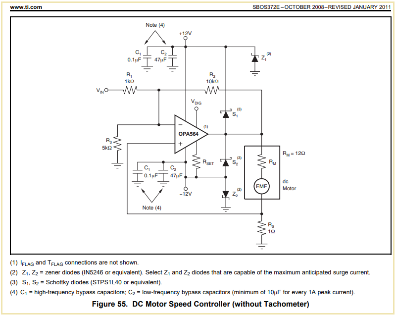
In the datasheet of the OPA564, Fig. 55, there are two Schottky diodes. I understand the goal of S1 : when a back-EMF increases the voltage on the output of the amplifier, S1 becomes forward and the current can flow towards the power supply.

But I really don't understand the goal of S2 : when the voltage on the output of the amplifier decreases and goes below -Vpower, S2 becomes forward, but in this case, where does the current go?

I tried to simulata it but it must be bad because the voltage on the ouput of the amplifier is the one of the simulate emf.

Thank you

  • Hi Sylvain,

    you mean this figure?

    If the motor emits a too high voltage, current is flowing through S1 to the +12V supply voltage. If the +12V supply voltage cannot absorb all of this current and the voltage rises up, Z1 becomes conducting and limits the positive supply voltage to a sane level by absorbing this portion of current the +12V supply voltage can no longer sink.

    The same happens if the motor emits a too low voltage. Then current is flowing from the -12V supply voltage through S2 into the motor, the cause of undervoltage. Please note that the -12V supply voltage is then sourcing current. If the -12V supply voltage cannot absorb all of this current and the voltage rises up negatively, Z2 becomes conducting and limits the negative supply voltage to a sane level by absorbing this portion of current the -12V supply voltage can no longer source.

    Keep in mind that a positive supply voltage is always sourcing current and can have issues with sinking current. In any case this will work as long as the net current is a current flowing out of the positive supply voltage. What happens when the net current becomes negative, so when current is flowing back into the output of positive supply voltage, depends on the regulator characteristics. Z1 is mounted to assure proper operation.

    Keep also in mind that a negative supply voltage is always sinking current and can have issues with sourcing current. In any case this will work as long as the net current is a current flowing into the negative supply voltage. What happens when the net current becomes negative, so when current is flowing out of the output of negative supply voltage, depends on the regulator characteristics. Z2 is added to guarantee proper operation.

    Kai

  • Hi Kai,

    Thank you for your answer.

    If I understand well, when the motor emits a too low voltage (means that the EMF is negative, right?), the output voltage of the amplifier can goes under -12V, which is a problem for the amplifier. So, in this case, S2 becomes conductive in order for the negative supply to compensate the decrease of voltage at the output of the amplifier. And, if the voltage continues to decrease and the negative supply can no longer give enough current, so Z2 becomes conductive, so the ground can provide current to compensate. Is that okay?

    Thank you

  • Correct Relaxed

    Kai

  • Hi Sylvain,

    Thanks Kai for the detailed explanation!

    Please keep in mind that S1, S2, Z1 and Z2 are a part of the external current steering protection circuitry for OPA564 when driving inductive load or motor application. Schottky diodes in S1 and S2 need to be low forward voltage drop and faster switching types than the ESD protection diodes that are integrated at the output of OPA564 terminal. 

    If you have additional questions, please let us know. 

    Best,

    Raymond

  • Than you very much, it's very clear !