This thread has been locked.

If you have a related question, please click the "Ask a related question" button in the top right corner. The newly created question will be automatically linked to this question.

OPA2388: Amplifier stable from -55 to ~85C, then significant drift.

Part Number: OPA2388
Other Parts Discussed in Thread: OPA2387, TINA-TI, LMP2012, OPA2333, OPA2392, LMC6482

Good Day TI,

I've linked this question to a topic where someone was having a relatively similar issue.  Unfortunately, they never confirmed if a solution was found.

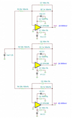
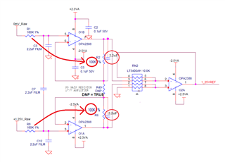
I've got a design using multiple OPA2388 amplifiers.  1.250000V is sent to this board from an external precision reference.  Unfortunately, it could be offset from /Ground/, so this signal is sent through amplifiers in an INAMP configuration to both buffer and reference it to system ground.  It is then sent through additional amplifiers in inverting configurations to generate -62.5mV, -25mV and -50mV.

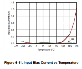
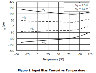
The circuit works very, very well from -55 to ~85 degrees C.  Above 85, however, we suddenly see a very significant decrease in the output voltage of our mV signals.

Is there anything inherent to the OPA2388 that causes a shift in parameters around 85C?  Our components and layout are all very high quality (film caps on the input voltage, C0G on the amplifier output, matched pair resistors for gain, etc), 6 Layer board with well thought out ground planes.  +2.3/-2.5 supplies are stable and quiet over the temperature range.

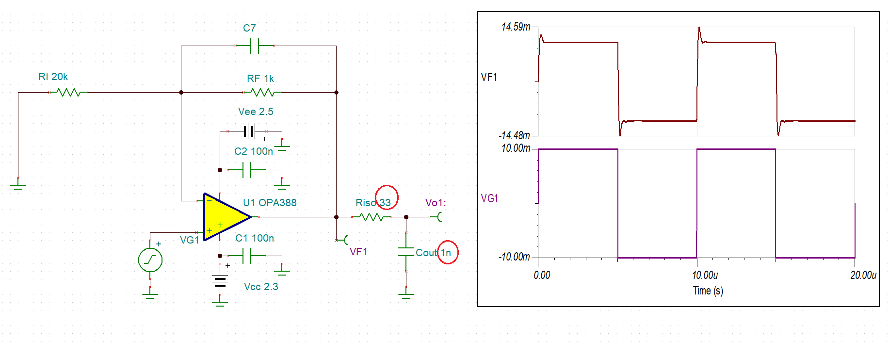
I've attached the schematic here and would appreciate some feedback.  We are open to changing to a different amplifier.  OPA2387 does look quite suitable, for instance.

Absolute input offset is important, but drift over temperature and time is much more so.  We can calibrate out any fixed offset error, but we only have a limited range of acceptable values, so offset can't be too significant.

Thank you very much.

AMPLIFIER.pdf

  • Hi Benjamin,

    This is an interesting one. I will check with the lab and see if I get high temperature performance data in this part. 

    In addition, could you provide us with more data. I am interested to know if the drift is resulted from 1.250000V reference voltage or the latter circuits. 

    You have one precision reference and three outputs from the reference voltage. I'd like to see if the ratios of -62.5mV, -25mV and -50mV output voltages are tracking before and after 85C. This may help us to locate issues in the design or components and/or others. 

    OPA388 Over 85C Drift 09172021.TSC

    Best,

    Raymond

  • I believe the issue is caused by the unmatched input impedances between the input terminals, which typically is required while using large resistors with chopper stabilized amplifiers like OPA2388; in order to minimize the commutation of IB current across the input resistors into voltage error, matching impedances is needed.  Also, since OPA2387 is more forgiving, it would be a good idea to use it instead of OPA2388.  Regardless, you should matched the input impedances as shown below; additionally, using smaller resistors like 10k instead of 100k will also improve the performance. 

    The problem becomes more acute at higher temperature because above 85C the input bias current, IB, becomes dominated by leakage of the ESD diodes and rises above IB chopping current level, which exaggerates the voltage drift - see below.

  • Marek,

    Thank you for the information.  I was actually beginning to come to the same conclusion.  I believe we will try swapping the input resistors to 10K.  I've also ordered a few OPA2387 parts to try in this circuit as well.

    Collecting some data shows that virtually all of the drift is caused by the first stage Instrumentation amp section.  The mV Signals track almost perfectly with the output of the first stage and only show a fixed error that doesn't change with temperature.

    We'll change the resistors, take some additional data, and then swap the op-amps and do the same.

    Thank you for yours and Raymond's help.  Very much appreciated.

    Best Regards,
    Ben


    VREF_TEMPERATURE_SWEEP.pdf

    VREF_TEMPERATURE_SWEEP_PERCENT.pdf

  • Marek,

    I updated the circuit with 10K input resistors and 2.2uF feedback caps.  It looks as if you were exactly correct in your belief as the matched impedance helped tremendously.  There's still a bit of a dip at high temperature, but it's a lot less significant.

    Based on the captured data, I'm inclined to believe that a swap to the OPA2387 will further improve the high-temperature performance because of it's lower and flatter input bias current.  Would you agree?  Is there anything additional that you can suggest to further eliminate the high-temperature roll off?  Unfortunately, there's always going to be some minimal input impedance mismatch because we can't predict the resistance of the wire bringing the 1.250000V into the board (variable length), but it should never be more than around 50 Ohms.

    Was there a particular reason that you chose 2.2uF for the feedback capacitors?  Would 2.2uF be a better choice than the 0.1uF for the second stage amplifiers as well?

    Do you think there's benefit to adding impedance matching resistors to the second stage amplifiers as well (shown in attached schematic), or do you feel that the input impedance of those signals is low enough to be largely irrelevant?  This design is very, very space constrained, so adding parts with no value is not something I want to do, but if there's benefit to be had, we'll find a place for them.

    In order to make up for some of the input filtering lost by switching to 10K input resistors, what are your thoughts on some capacitance at the inputs to O2A (C90 and C91 in the attached schematic)?

    Are there any any other changes to the circuit that you might suggest for best DC performance over temperature?  Are the 0.1uF X7R supply capacitors and 33 Ohm/1000pF C0G output filters reasonable choices in your opinion?

    Thank you very much for your assistance.  I can honestly say that rapid feedback like this is what leads me to so frequently specify TI parts in my designs.  TI support has always been excellent, and please know that it's appreciated.

    Best Regards,
    Ben

    0160.AMPLIFIER_REVB.pdf

    0245.VREF_TEMPERATURE_SWEEP.pdf

    2311.VREF_TEMPERATURE_SWEEP_PERCENT.pdf

  • Ben,

    I'm glad to hear that my recommendation helped to solve the problem - OPA2387 should do even better not the least because of its lower IB at high temperature.  Matching impedances in the second stage may also help, I just wasn't sure what resistor values you used in the second stage. 

    You also have to make sure that the total values of the input and feedback impedance are equal - see below.

    In order to make up for some of the input filtering lost by switching to 10k input resistors from 100k, you should simply increase the values of capacitors by 10x (btw, what is the reason to set the corner frequency below 1Hz?) The 0.1uF supply bypass caps sound reasonable and your choice of 33ohm and 1000pF is good from stability point of view, which results in ~21% small-signal overshoot (<25% is good) - see below.  

    However, with the first stage filtering below 1Hz, fc=1/(6.28*100k*2.2uF), if you want to minimize the total integrated noise at the output, using 33ohm and 1nF sets the bandwidth at much higher frequency of around 4.8MHz, fc=1/(6.28*33*1nF) so it would probably make sense to set the output low-pass filter at much lower frequency by increasing Riso and Cout values - see below.  For example, increasing Riso and Cout to 1k and 1uF, respectively, results in 159Hz bandwidth and assures good circuit stability (hardly any overshoot) - see below.  

    I have attached below Tina-TI so you may run your own transient stability analysis. 

    Ben OPA388 transient stability.TSC

  • Marek,

    Once again, thank you for the information.  I will run some simulations to determine the best filter solution, but I've marked your answer as a solution because I now have all the information I need to proceed without assistance.

    To answer your question, the input filter was set to a very low frequency because the incoming signal is pure DC and the environment we are operating in has a number of fairly significant noise sources in the Hz to Tens-of-Hz range.  It's probably not necessary that it be as low as it is.

    I will post a response with the data capture of the OPA2387 tomorrow to close out this thread in case it is useful to anyone else here.

    Very much appreciate your assistance, it was timely and invaluable.

  • You are welcome.  Good luck.

  • Marek,

    We received the OPA2387 parts today and swapped them out.  Very surprisingly, they made no difference.  They have the same fall off at the same exact temperature.

    Any thoughts as to why that might be?  I had expected a rather significant improvement.

    Best Regards,
    Ben

    6433.VREF_TEMPERATURE_SWEEP.pdf

    0777.VREF_TEMPERATURE_SWEEP_PERCENT.pdf

  • Marek,

    Additional information.  I swapped out the 10K resistors with 4.7K resistors (R1, R2, R6, R8).  The output dip at high temperature reduced by almost exactly half.  So it looks like it's still IB current related.

    I know the OPA2387 is a very new product - is it possible that the datasheet numbers for IB are calculated and not measured, and therefor incorrect (or, alternatively, perhaps the OPA2388 was actually much better than datasheet specifications)?  It seems to behave identically to OPA2388, though the datasheet would lead me to believe it should be much, much better in this regard.

    Although I could further reduce these resistors (to, say 1K), I'm wondering if a completely different approach is warranted.

    Perhaps something like a LMP2012 would be a better choice for this application?  Still low offset and low temperature drift, but orders of magnitude less IB (although I am making a big assumption here since there's no IB specification at other than 25C in the LMP2012 Datasheet)

    I'd be interested to hear your thoughts.  I'm not opposed to a complete rip-up of this circuit, as getting it right is the most critical section of this entire design.

    Thank You,
    Ben

    7180.VREF_TEMPERATURE_SWEEP.pdf

  • Marek,

    Sorry to barrage you with replies, but I figure too much information is better than not enough.  Additional Plot using 1K input and feedback resistors.  As expected, the drop at temperature was again reduced.  Unless you believe another factor is at play, it would seem this is directly related to IB.

    5556.VREF_TEMPERATURE_SWEEP.pdf

    1805.VREF_TEMPERATURE_SWEEP_PERCENT.pdf

  • Yes, all what you see is IB current related but there are two distinct components to IB current in chopper amplifier like OPA2388 or OPA2387 - integrated current coming from the IB spikes of chopping action of the amplifier front-end that dominates the total IB up to 75C-90C and then reverse-biased leakage current of ESD protection diodes that takes over above 90C.

    All datasheet specifications are tested at room temperature (25C) while at higher temperature they are specified by characterization - see note 1: Specification established from device population bench system measurements across multiple lots.

    The resistor matching in chopper amplifiers helps mostly with IB mismatch coming from chopping action but not necessarely due to leakage, thus it may not help above ~85C.

    Therefore, it looks like you simply need precision op amp with lowest IB at higher temperature and LMP2012 is not one of them - see below.

    OPA2333 has the lowest IB over temperature for chopper amplifiers - see below.

    However, non-choppers, like PA2391 or OPA2392, would be your best choice (see IB vs Temp below) but for now only single versions are available.

    Thus, I believe LMC6482 dual may be your best choice - see below.