This thread has been locked.

If you have a related question, please click the "Ask a related question" button in the top right corner. The newly created question will be automatically linked to this question.

OPA140 Ibias

Other Parts Discussed in Thread: OPA140


Hi people


I have an electrochemical application where i need to measure current in a wide range (microamps to picoamps) and im going to do it with an I-V converter based on the transimpedance amplifier.


I have two devices pre-selected (the OPA140 and the AD795), the OPA would be my choice because of its great characteristics (specially when it comes to offset, and the error produced by it on the current), however, when i compare the Ibias of the device, it has 5 times worst performance than the AD795 (worst case scenario that is)


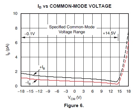
However, the only graphic on the datasheet about the Ibias (Figure 6 on the datasheet), shows that the Ibias change with Vcm but the limits are basically the supply limits.  So, i want to ask you, is that a mistype on the datasheet?  or can i use the device with the 2pA max Ibias because i will not have more than 15Vcm on my circuit


Thank you very much and best regards

  • JACR,

    I believe you are reading the maximum specification in the table, +/-10pA. The data in figure 6 is typical performance data. There is often a large difference between typical performance and our specified maximum on input bias current. This allows for possible process variation and the difficulties in testing very low input bias current in a production environment.

    Regards, Bruce.

  •  

    Hi Bruce, and thank you very much for your answer...  Yes, im talking about the maximum specifications (+/-10pA); i understand that would be the case with the "worst" devices in a production lot, however, i need that spec for my worst case calculation and the  resolution of the final equipment  (just imagine, if its dificult for TI testing the low Ibias, how about for us mere mortars :)

    I was looking for more info on the datasheet of the OPA140, but the only graphic i saw about it, was the figure 6 (Ibias vs Vcm).  If you see, the limits of Vcm, are +/-18V, that are the maximum supply voltages for the circuit, so, im asking if it was possible that the graphic is meant to be Ibias vs Supply Voltage.

    Now, if the graphic is correct (as im 99,9% sure it is), i can basically say it will work most of the time with an Ibias lower than 2pA because i will enclosure the PCBs on a faraday cage, and i will not have significant values of Vcm; also, the size of the input signal will be lower than the supply voltage (+/-15V) and i will use the OPA140 as a transimpedance amplifier (which output would be limited to 10V, as that is the input range of the converter)

    Thank you very much for your time and your answers


  • JACR,

    Figure 6 appears to be correct. This is the common-mode voltage, not the power supply voltage.

    I think you are confusing the common-mode voltage with some type of environmental noise. The common-mode voltage in this case is the DC voltage on the inputs. And what really matters, in this case, is the voltage relative to the positive power supply voltage (18V in Figure 6). Our data sheet might have been more clear if it had labeled the x-axis as V+ on the right-hand side with successive labels of (V+)-1V,  (V+)-2V.... etc. That would call attention to what really matters.

    In an I-V converter circuit, the DC voltage on the inputs is probably very constant. The critical factor here is that when the difference between the C-M voltage and the positive power supply becomes less than 3V, or so (difference between 15V and 18V in Figure 6) the input bias current goes up significantly. You probably have (or should have) much more than 3V between the C-M voltage and the supplies so you are in a healthy region of operation. Notice that this region is outside the specified operating range of the OPA140. Specs assure operation to withing 3.5V of the positive supply voltage.

    Is this clear now?

    Regards, Bruce.

  •  

    Thank you very much Bruce

    I was taking into account both the Input Common Mode Voltage Range and some Common Mode Voltage that could appear (in a noisy environment that is), but i wanted to know if the Ibias was dependant of the supply voltage.


    Your answer was pretty clear and now im sure that the OPA140 is my choice, because it offers better performance for Rf<100MOhm (the ones that i would be using).  


    Best regards