This thread has been locked.

If you have a related question, please click the "Ask a related question" button in the top right corner. The newly created question will be automatically linked to this question.

OPA4388: 2 OPAMP in the same IC (i.e 2-channel OPAMP like OPA2388): may I expect the 2 parts have a very close values for Voffset, Ibias and Ioffset?

Part Number: OPA4388
Other Parts Discussed in Thread: TINA-TI, INA333, OPA333

Hello,

I am dealing with a high impedance sensor with uV output, to be specific a thermopile. I need a gain between 800 and 1000 so the values of input offsets of the amplifier are very very important.

I am testing the circuit with OPA4388, using a single channel to amplify the sensor output.

The problem is about the stability of the output when the input is 0: my SW corrects the offset, saved during calibration but it is not constant after power-on and it changes with the subsequent further power on. There is a little variation, maybe due poor EMI shield (it is still a prototype board) but what's worrying me is that the average value changes each time I power on and generally decreases during operation.  

The use of the instrumental input (2 o 3 OPAMP) should reduce the offset, but only if the values are similar for the 2 OPAMPs at the input: then I am wondering if the values of Voffset, Ibias and Ioffset are nearly the same if I use the OPAMPs in the same IC.

So, with a quad OPAMP like OPA4388 I can have a 2-OPAMP instrumental amplifier, the amplifier for NTC and the buffer for the common voltage (sensor can have output both polarity).

I do not really care how much is the effect at the output, I care it is the same every time I power on and during operating....

Thanks

Maurizio

  • Maurizio,

    There is no correlation between Vos, IBs and Ios in two channels of a dual or four channels of a quad - they are completely uncorrelated (the same as two or four single op amps).  Thus, the only thing you may be certain about their magnitude is that they all meet max/min limits specified in the datasheet. In general, no correlation in specs between different channels of the same package is true of any spec that is centered around zero.

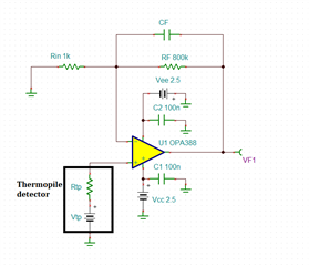
    There are several potential reasons behind instability of OPA4388 output in thermopile application, including the type of thermopile element used, thus the devil is in the detail and for this reason in order to assist you we need to see your detailed schematic. Below you may see a typical thermopile application circuit in gain of 800 but one thing to know about chopper amplifiers like OPA4388 is that in order to minimize commutation of the IB chopper spikes into offset error they may require matched input impedances between two input terminals. Also, in order to minimize fluctuation of the output, you may have to use a low-pass filter at the output of the amplifier with corner frequency way below 1kHz.

    Attached please find the typical thermopile Tina-TI schematic.  If you need further assistance, please provided the necessary details by modifying it.

    OPA388 thermopile detector circuit.TSC

  • thanks, Marek

    Really I have the same circuit as you, the only difference is that the power supply is single 3 V and the virtual ground is at 250 mV: you know, sensor can give both positive as well as negative signals.

    So, I connect the ground points of your schematic to the output of an OPAMP as buffer. But the impedance of my sensor is 43 kOhm, then I cannot match the 2 inputs with so high value having a gain ~800. So, like you suggest, I have used 1k / 820 kOhm .... 

    Now, I'm gonna waste your time asking if with a 2-opamp instrumental amplifier the situation will be more stable....

    I'm sorry, currently I am on holiday until October 8th, so I cannot give you the current schematic and its possible improvement like I have thought.

    Thanks for now, I'll come back as soon as I'm in office again.

    Maurizio

  • Hello Marek,

    I have come back office yesterday, so today I can send you the schematics I have told in my previous message.

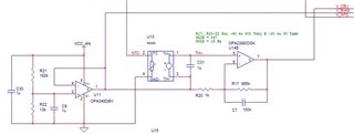
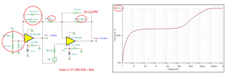
    The 1st one is the current schematic, like you sent me: you can see that the components are really the same!

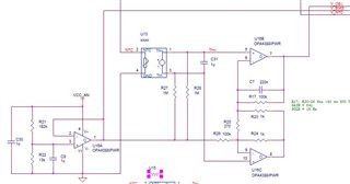
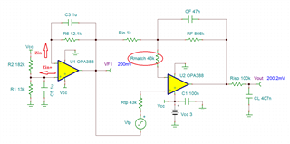
    The second one is the other topology I have thought due the 43 kOhm resistance thermopile which makes difficult to match the input impedance with a single OPAMP.

    What do you think about? Will the 2nd one give a better behavior with offsets? Or it is needed the classic 3-OPAMP instrumental amplifier?

    I recall you that currently, with the 1st schematic, the offset is not constant, it changes for different power on and during on time.... Sob

    Thanks

    Maurizio

  • Maurizio,

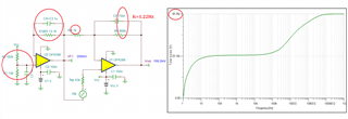
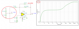
    I have simulated your customer's circuit with couple of edits to match input impedance of first buffer and get total noise of 50.36uVrms-see below.

    Matching input impedances of the second op amp results in a lower 44.42uVrms total noise mainly because of the lower fc of 0.064Hz feedback filter.

    Adjusting CF to match fc of 1.22Hz in your original circuit results in total noise of 56.71uVrms (vs original 50.36uV) - see below.

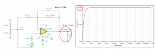
    However, there is no good reason for the front-end buffer because the Vtp is measured differential - eliminating it results in total noise just slightly higher - 58.77uVrms.

    I do not believe that the second difference circuit will give you better results.  If your customer really wishes to further lower the noise, the way to do it is to add a low-pass filter at the output - see below total noise of 19.45uVrms.

    3157.OPA388 thermopile detector circuit.TSC

  • Marek, 

    I don't have anything different from saying thank you a lot but ....

    It is not the noise at output which worries me, it's the effect of the Voffset,and Ioffset that I wanna limit.

    The noise of 50 or also 100 uV will make just +/- LSB at the ADC output, than it can easily filtered by SW.

    What the SW cannot filter by itself is the static output at 0 V from the thermopile that could arrive in theory up to +/-7uV +/- 1 nA * (Ri+ + Ri-), from OPA4388 data sheet.

    It is the second term the heavier which values up to 1 uV/kOhm then, like other TI literature suggests, better to do not match the input impedance.

    In case I use 1-opamp amplifier, the possible bias voltage is up to +/- 51 uV and, so,  +/- 44 mV at the output ( +/- 241 ADC counts!!!!). 

    Fortunately, in  my sample it's around 32 ADC counts, ~ 6 mV at output which means ~7 uV at the input but I am looking at just 1 sample at room temperature.

    And, again, it appears that the offset is not constant between different power on and also during the normal operation which bring a variation of 1.2 °C in the readings at the very same temperature of the black body. Still in my unique prototype.

    The so-called "instrumental amplifiers" are topologies based on 2 or 3 opamp whose benefit is the input that can match high impedance sensors and the "cancelling" of the biases at the inputs. Now, while I'm pretty sure that the 3-opamp topology has an output bias mainly related to the last stage (there are plenty of applications explained and it is the same topology adopted for INA333) I do not find anything about the 2-opamp topology; look, due the limited space on the sensor board, I would prefer to use the 2-opamp rather than the 3 opamp.

    Thanking you again for your suggestions and help, I'll wait for your next advise, apologizing for not having well focused my problem from the beginning!

    Maurizio

  • I think you have overlooked part of my initial answer: one thing to know about chopper amplifiers like OPA4388 is that in order to minimize commutation of the IB chopper spikes into offset error they may require matched input impedances between two input terminals - thus, even if you filter out the noise you will still be left with DC offset error.  Btw, other TI literature suggesting not to match the input impedances applies to linear CMOS op amps but not to choppers - need to match input impedances in choppers is analogues to similar need to match them in the bipolar input transistor op amps with no IB cancellation.

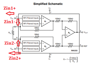
    As far as your claim that it's easier to match input impedances in instrumentation amplifier, I do not believe this is true. The matching must be between the Zin1+ and Zin1- as well as between Zin2+ and Zin2- and NOT between the Zin1+ and Zin2+ (see below).

    Having said that, INA333 (and OPA333) is much more forgiving and you may be fine using it without attempting to match the input impedances. One concern would be its much lower bandwidth but this should not be a problem due to low speed of the application (fc=1.22Hz).

    All in all, whatever the total offset is in your circuit it should not change between different power on cycles; thus my question is, what is the actual magnitude of "a little variation, maybe due poor EMI shield" and have you confirmed whether it's not part of an extrinsic noise picked up from outside environment? 

  • Ok, Marek, I guess to have learnt the lesson.

    i have spend some time to look into bias compensated non-chopped opamp but I have not found anyone which can help me to minimize bias and the drift with temperature, then I remain on the OPAx328 ....

    So, I have also learned that the 2- or 3-opamp instrumental topologies help me to reduce the CM noise but they won't make my life better than the solution with a single opamp for the features I need.

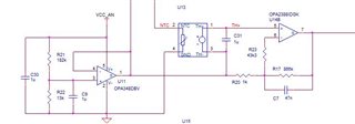
    Then, I suppose the best choice is to use a circuit like you suggested the 1st time (the very same I started) with a little correction to match the high input impedances or as much I can. Look this circuit below and give me your feedback, please ....

    The resistor R23 added in series at the - input should nearly match the impedance at the + input, shouldn't it?

    Thanks again for your time ......

    Maurizio

  • Maurizio,

    Adding a matching 43k resistor in series with negative input should match the input impedances of the second stage at the expense of higher noise but this may be mitigated by adding a low-pass filter at the output - see below. Also, for the same reason you match the input impedances in the second stage, you should do the same in the first stage by making Zin+ and Zin- equal.  However, since first stage matching of G=1 is not as critical as matching of the second stage with G=866, you may neglect it.