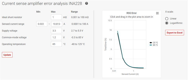
Other Parts Discussed in Thread: INA228, SYSCONFIG
Hi
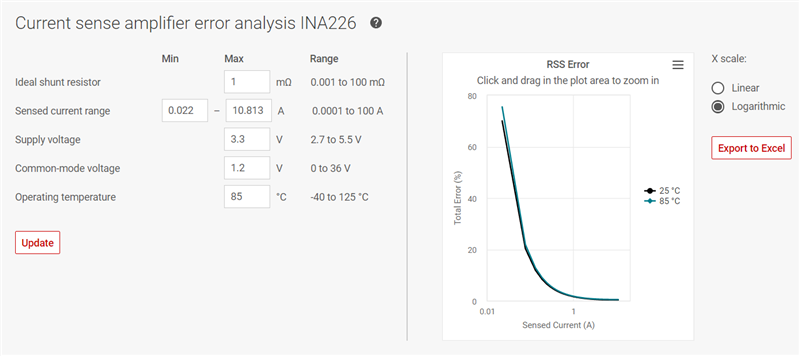
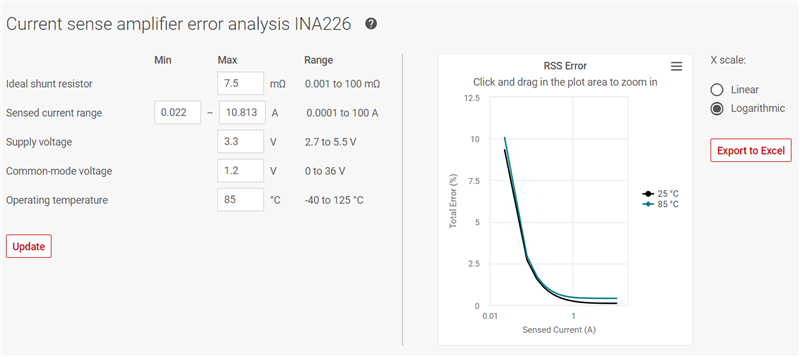
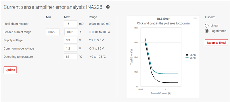
We are using the INA226AIDGST power monitor IC in our design and we are reading power and current register value which are not satisfactory so find below attached image as well as our max current and voltage table.
suggest how to slove this problem.
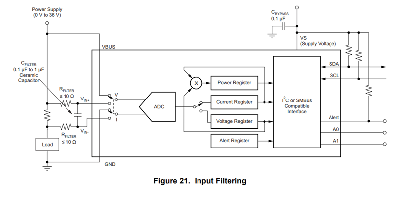
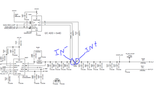
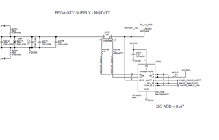
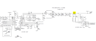
R3507 Current sense value is 0.001E and INA226 communicate through I2C with FPGA Board.
Voltage and current table information.

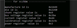
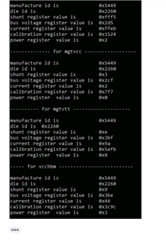
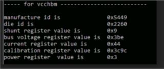
Below are the result which we have getting during testing on our board.
All result in hexadecimal.
Power LSB Value as per below one

Below are the result which we have getting during testing on our board.
All result in hexadecimal.