This thread has been locked.

If you have a related question, please click the "Ask a related question" button in the top right corner. The newly created question will be automatically linked to this question.

THS3092: Rise time issue at output of op-map

Part Number: THS3092
Other Parts Discussed in Thread: THS3217, THS3491, THS3062

Hi,

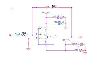
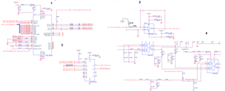
We are using THS3092 op-amp part in our design as inverting amplifier configuration.


Attached schematics shows op-amp configuration used in design.


Input of op-amp given from DAC output and its voltage ranges between 0 to 1V.


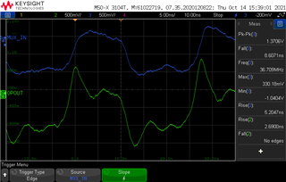
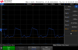
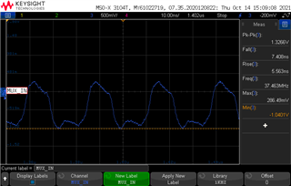
When input of op-amp switching from low to high observed normal output.


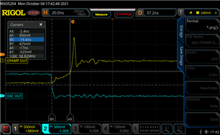
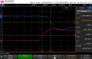
But when input of op-amp switching from high to low at op-amp output seeing glitch also output having around 20nS rise time.


Also attached oscilloscope image of the op-amp input and output side captured during input high to low and low to high condition,


Kindly provide any solution to remove this glitch.


Note: Output of op-amp connected to 50ohm load.


Regards,

Vinayak Arkachari

  • Morning Vinayak, 

    That is an unusual spike. only being on one side of a square wave suggests the operating point prior to transition is somehow different than on the other edge. Hard to tell your actual final output VI on each side of the square wave - that would perhaps help - in the meantime

    1. That is a pretty fast edge coming in, perhaps filtering it a bit might help

    2. The THS3092 is quite old (and a dual, is the other side set up benign)

    3. I had driven an upgrade path with the THS3217 and THS3491 - while in development, the customers we visited noted all prior solutions would be obsolete once they came out - well they are out, you might consider them - I know there is a big price delta, but they are both >15yrs newer

  • I also just noticed the right scope plot was on a Keysight scope and the left on a Rigol? Probably not the issue, but you might try the problem test on the Keysight scope as well. 

  • Hi Michael,

     Thank you for your response.

     We already measured in keysight scope there also we are seeing similar behavior.

     Is there any filtering circuit for this issue.. Please suggest.

    Regards,

    Vinayak Arkachari

  • Need more ckt detail, most Dacs are complementary out, how you handling that into the amplifier, more complete schematic required including loading. You say 50ohm load, is that doubly terminated or just a single 50ohm to ground - scope input or what? 

  • Hello Vinayak,

      The low to high rise time from the DAC estimates to be around 2.4ns. But for the high to low fall time from the DAC, I can't really tell due to the lower division setting. But, it looks to be around 2.5ish ns as well. I agree with Michael that it is very strange for their to be an overshoot on only one case. 

      But, I noticed power supply rails are 5V to ground, and common mode input voltage is 0V. This device is not a rail-to-rail amplifier at either the input or output of the amplifier. Also the minimum total supply range for this device is 10V.  I would suggest trying this at -5V to 5V supply rails. 

      Anyways, the bandwidth required for this pulse rise/fall time would be around 140MHz, and the slew rate needed is around 400V/us. So, like Michael said, you should use either THS3217 orTHS3491.

    Thank you,

    Sima

  • Oh yes, +/-5V on this device is barely operating - retest your step with at least +/-7.5V supplies. 

  • Hi Michael,

     Here attached full circuit, termination is single  50ohm to ground. 

    Currently +5V and -5V supplies are connected to device, i will try with +/- 7.5V supplies.

       Regards,

       Vinayak Arkachari

  • Hello Vinayak,

       Let us know how the increase in power supplies goes. Thanks for sharing the full schematic with us. It looks like the amplifier is driving a multiplexor, I would suggest adding a 50-100 series resistor at the output of the amplifier. This is because to avoid instability of the amplifier due to driving a load capacitance with a low series on resistance multiplexor. This app note explains this issue in more detail.

    Thank you,
    Sima 

  • Hi Sima,

      One more observation i had when we probed mux input pin and multiplier input pin not seeing any spikes.

       Earlier i probed at opamp output pin, also attached images for reference.

    Regards,

    Vinayak Arkachari

  • Hello Vinayak,

      Thank you for the additional images. Probing directly at the amplifier output pin is not recommended due to the issue on capacitance loading that was brought up earlier. Adding a series resistor between 50 to 100 ohms at the output of the amplifier should help eliminate your spike issue.

    Thank you,
    Sima 

  • Hi Sima,

     Sorry for the late response i have tried with adding 50ohm resistor at opamp out put.

     When we probed at at destination side still we are observing some overshoot and also i am getting 5nS rise time and fall time.

    When we did spice simulation for this part in simulation we observed around 1nS rise/fall time.

    Regards,

    Vinayak Arkachari

  • Hello Vinayak,

     Thank you for implementing the suggestions. Are you probing at the 50ohm at the output of the amplifier or is this at the input of the mux? Also, from earlier scope shots, it looks like the DAC output has similar overshoot. Could you measure at the input of the amplifier as well for comparison?

     For the spice simulation comparison, it will depend on other parasitic on the board as well as the input signal characteristics. Would you be able to share spice simulation file? From earlier, the calculated bandwidth/slew rate needed for 2.5ns is 140MHz and 400V/us (for same output considerations). So, a 1ns rise/fall time will need a higher capability. For an easy p2p (same pin/package as THS3092) test, try out the higher bandwidth THS3062. But, as Michael suggested, would looks for a design revision using the THS3217.

    Thank you,
    Sima