This thread has been locked.

If you have a related question, please click the "Ask a related question" button in the top right corner. The newly created question will be automatically linked to this question.

Current Sensing Amplifier

Other Parts Discussed in Thread: INA190, INA186, INA240, TIPD104, INA326, TIPD135, PGA281

Hi,

I am looking for a current sensing amplifier design. TI found many solutions on the TI website. These are my requirement ,

Operating Voltage: 3.3V

Load Description: Sleep Current 2uA; Uplink Current: 300mA

Please suggest to me a suitable current sensing amplifier solution that works for my design.

Amplifier output I would like to connect to the microcontroller ADC port [ 12bit ADC ] to sense the voltage in the form of current.

Regards,

Rahul K V

  • Rahul, I have several questions here to make a good recommendation foe you:

    - Can you expound on what you mean by uplink current here? Are you attempting to measure a total of 300mA?

    - What is the total range of current you are looking to measure here? I.e., what is the min and max current values you expect in your system?

    - Do you need any built in functionalities, such as comparators for OCP?

    - What is the common mode voltage you expect to pass over the shunt over the device, and do you have a power budget for this system?

  • Hi Carolus,

    Here is my inline response. Please have a look and suggest me the suitable design.

    - Can you expound on what you mean by uplink current here? Are you attempting to measure a total of 300mA?

    Rahul: Yes,300mA is my device maximum load current

    - What is the total range of current you are looking to measure here? I.e., what is the min and max current values you expect in your system?

    Rahul:2uA - 300mA

    - Do you need any built in functionalities, such as comparators for OCP?

    - What is the common mode voltage you expect to pass over the shunt over the device, and do you have a power budget for this system?

    Rahul: Operating Votage: 3.3V

  • Rahul,

    For measurements this small, the only current sensor in our portfolio capable of microamp resolution is the INA190/INA186 family. This is because these devices typically require larger input bias currents than a traditional op amp to power the front end allowing common mode in excess of the supply voltage. 

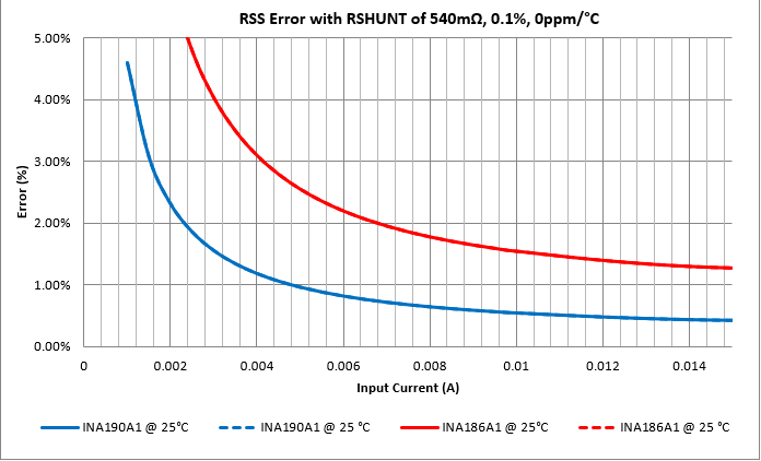
    The above said, this is a very difficult amount of resolution to achieve here. You are looking to measure a current with a resolution differential of 150,000:1. Typically, this is not achievable with a single device, and the reason is due to full sale range restrictions on the device (any device for that matter), and the error that the offset brings at lower bounds of measurement. For example, here is a representative error curve of the INA190 for these parameters:

    You can see that the error is already >4% at about the 1mA mark, and this is using a 540mΩ shunt chosen to maximize the output at the 300mA mark. The device simply will not produce enough shunt voltage at the lower end to not be dominated by the offset voltage. Therefore, I would most likely look for at least a 2 device solution and break the measurement range up to be able to achieve this. 

  • Hi Carolus,

    Yes, I will go with 2 separate circuit solutions to measure the High current and low current. Can you share with me a few reference circuit / Part number that works for this application? The selection of appropriate shut resistor, Power supply Noise removal ..Etc . Please share design references and guidelines to complete the design.

  • Rahul,

    On the analog side of the house, the only device(s) capable of measuring down to uA resolution are the INA190/INA186 family due to the bias currents. You would need to use this device for the lower range of measurement, and then something like INA240 on the upper end to handle the second part of the measurement range. Regarding shunt selection, PSRR, etc., you ultimately need to select a shunt that fits your application needs based on power levels. I recommend checking out our video series here for answers to these types of questions. 

    Depending on your accuracy needs at the lower end, you may also look at some instrumentation amplifiers, such as this design here: 

    TIPD104: This TIPD uses the INA326 on the low side. There is a switch that changes the gain of the device once, which allows for the sensing of 3 decades of load current. Please note that this Precision Design was only simulated.

    TIPD135: This TIPD uses the PGA281 on the high-side to sense 4 decades of load current (10uA-100mA). It is supplied with +/-15V.

  • Hi Carolus,

    We have implemented the sleep current measurement circuit and here is the observation,

    1. We used 2 amplifier IC connected back to back having the different gain setup,

    INA190 (500V) + INA 190 (25V) These are the gain. The reason is my ADC _MCU is not able to capture because of the 12bit resolution and this is how we built it. Please correct if i am wrong or any other better method or solution 

    2. We have built the circuit as per the above described having the resistive load (2uA) and we see the output voltage is varying / fluctuating and unable to capture a constant value. Please check

    We need a solution and Why the second amplifier output is fluctuating and not able to get the fixed millivolt even after having the fixed resistive load

  • Rahul,

    Would it be possible to see a schematic of your setup here? Also, which amplifier is showing the fluctuation, and in what state, and in what amount? Is it possible to also get a scope shot of thus fluctuation?