This thread has been locked.

If you have a related question, please click the "Ask a related question" button in the top right corner. The newly created question will be automatically linked to this question.

OPA564: Paralleled operation

Guru 11940 points

Part Number: OPA564

Hello,

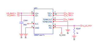
My customer designed a circuit using two OPA564s for paralleled operation as shown below.

VCC_LD : +5V / VEE_LD1 : -3.3V

1. Please review the OPA562 design for any issues.

2. When they used one OPA564 the max current of -3.3V was 24mA. However, when using two OPA564s, the max current \of -3.3V was 600mA.

    Please let us know why there is a difference in current consumption.

Thank you.

JH

  • Hi JH,

    Paralleling two or more op amp outputs directly may not result in the expected behavior such as simply twice the output current. There are electrical differences between each individual op amp such as voltage offset that can upset the circuit operation. Usually this is observed as unequal op amp currents and uneven heating of the op amps. Most often, when a designer attempts to parallel op amps outputs they use circuits that incorporate ballast resistances to help balance the current between the op amps.

    Here is a discussion on the subject from the TI e2e archives:

    https://e2e.ti.com/blogs_/archives/b/thesignal/posts/paralleling-op-amps-is-it-possible

    The operating current difference that you are having with individual OPA564 op amps versus when the same two op amps are operated in parallel are drastic, 24 mA vs 600 mA. Something bigger is happening to cause that much of an operating current change. I have some questions about your circuit that may help explain what is happening in the circuit:

    • P21, EP on each OPA564 device in the schematic - Is this the package underside PowerPad connection? Note that the PowerPad is required to be connected to the most negative supply potential which would be VEE_LD1 in your schematic. It is shown being connected to GND. That would be a problem.

    • Op amp feedback - It is not clear how each OPA564 is obtaining negative feedback as connected. The left side OPA564 shows R221 (5.1 k) connected from the inverting input to the LD_BIAS1- point. The right side OPA564 shows R382 (5.1 k) connected from the inverting input to the LD_BIAS1- as well. LD_BIAS1- connects to R230 (0.2 Ohms) to GND. R221 and R382 do not connect to their respective OPA564 VOUT pins. If the op amps do not have feedback, the output would lock up at one rail or the other. Please explain how the feedback is accomplished.

    If the outputs of the two OPA564 lock up at opposite output rails one output would try and sink/source output current to the other and the current could be very high.

    Let me know what you find.

    Regards, Thomas

    Precision Amplifiers Applications Engineering

  • Hi Thomas,

    The customer's response to your inquiry is as follows.

    1. EP(P21) is open in PCB design.

    2. It is connected by the following path.

          OPA564 VOUT(LD_BIAS1+) -- LD1 Pin6(LD+) -- LD1 Pin7(LD-) -- R230(0.2ohms) -- GND

    Currently, the customer's OPA564 circuit is supplying 80mA to 1.8A to LD1, and there is no problem in LD1 operation.

    However, in the 80mA~600mA section of LD1, V-(-3.3V) of OPA564 consumes 400mA~180mA current, and in the 700mA~1.8A section of LD1, it consumes 45mA~39mA.

    Could this cause damage to the OPA564?

    If this symptom is not causing damage to the OPA564, the customer is trying to make a product using a negative power regulator with a -5V and 1A specification.

    Thank you.

    JH

  • Hi JH,

    I apologize some of the explanation provided is not clear to me so I need some further clarifications.

    • If the OPA564 backside PowerPad is floating instead of being connected to VEE_LD1 (V-) that can affect its operating and it may not be operating correctly.

    • You describe the signal path, OPA564 VOUT(LD_BIAS1+) -- LD1 Pin6(LD+) -- LD1 Pin7(LD-) -- R230(0.2ohms) -- GND. I am not seeing the feedback connection from VOUT Pin 5 and VOUT_1 Pin 6, back to IN- Pin 15. It would seem the correct connect would be from LD_BIAS1+ to LD_BIAS1- would connect the correct point together. The VOUT and VOUT_1 would be connected to the IN- input and the R230 0.2 Ohm load.

    • Regarding the output current you mention "in the 80mA~600mA section of LD1, V-(-3.3V) of OPA564 consumes 400mA~180mA current, and in the 700mA~1.8A section of LD1, it consumes 45mA~39mA." Where are the OPA564 400mA~180mA current and 45mA~39mA currents being observed in the circuit? If you could show how the two OPA564 op amps are being connected together and where these high current are being measured that would be help us understand if the currents are okay.

    • Are there any images of the input and output waveform for the two OPA564 amplifiers hardwired together? 

    I reiterate that the only way I have seen two op amps successfully connected for parallel output operation use the method shown in Bruce's e2e blog. 

    Regards, Thomas

    Precision Amplifiers