This thread has been locked.

If you have a related question, please click the "Ask a related question" button in the top right corner. The newly created question will be automatically linked to this question.

OPA818: Testing TIA without photodiode

Part Number: OPA818
Other Parts Discussed in Thread: TINA-TI

Hello,

I saw a question concerning how to test a TIA with a Network analyzer here: https://e2e.ti.com/support/amplifiers-group/amplifiers/f/amplifiers-forum/823092/how-to-test-tia-without-photo-diode/3045371?focus=true

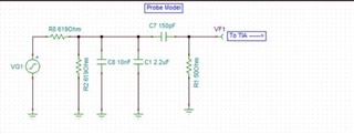
I saw the slides but was unsure about dimensioning the capacitors. For example, if you wanted to cover a signal band of 50 khz to 50 Mhz, would you be able to explain the dimensioning of the Cs?

cheers

dominik

  • Hello Dominik,

       Here a couple more references with in detailed explanation of testing TIAs without photodiodes:

    1. Explanation on Michael's PowerPoint with Capacitance Selection (Michael linked his pdf article which is very helpful for this type of measurement; linked again below) 
    2. Continuation explanation of above
    3. Testing frontend without photodiode and without amplifier

       More detailed explanation on the circuit based on the above threads: 

       The input side that Michael proposed works in order to simulate a photodiode input stage using a voltage source. The important aspect of simulating a stage like this would be to include the photodiode capacitance (C7 of 150pF). C8 and C1 with the resistor divider (R8 and R2) act as a low pass filter or a pole in the frequency response which compensates for the zero caused by C4 and feedback resistor (high pass filter). 

       In this E2E thread (1,3), Michael and Kai went of the assumption that your source voltage (usually from network analyzer or signal generator) will have a 50 ohm source. So to impedance match this 50 ohm source (R8), you would need R2 at also 50 ohms. Then they chose C8 or C1 depending on your bandwidth requirements. C8 and C1 can be combined as parallel capacitors, they had this separated because it is good practice when making a test board to give yourself more pads incase tuning is needed due to parasitic. As a close estimate, you can use RC filter concept to determine capacitance for the input bandwidth, in this case they picked around in the low kHz.

      Increasing R8 and R2 came about because in the first thread, the higher input capacitance for C8 with 50 ohm matching led to issues with the passband increasing at higher frequencies due to the lack of feedback resistor to create that compensation. So, that is the reason 10nF was kept, but the resistors were increased using again RC filter concept to obtain the lower input bandwidth in the Hz.

      I use this calculate for an estimate: http://sim.okawa-denshi.jp/en/CRlowkeisan.htm. Then I use Tina-TI to simulate AC response to tune values. But Michael’s article that he linked “Here’s an Easy Way To Test Wideband Transimpedance Amplfiers” goes into detail on the transfer functions and calculating the capacitors to obtain maximally flat passband.

      (Below in reference to thread 1 on Michael's comment on self resonance)

      Michael meant by self-resonance is regarding the capacitor and its series inductance due to its packaging. This may happen before the expected cutoff frequency which will result in an increased current going through the series capacitance (C7). In the frequency response, this will appear as a peaking at a certain frequency. We want to avoid this occurring before the cutoff frequency, and “push” this resonance into the higher frequencies. So choosing C1/C8 carefully here for that reason, which is also why Michael suggested putting in estimated inductors in series to these capacitors for a more accurate simulation. But, Michael's article will again include the most accurate transfer function accounting for these inductances.

       This is a lot of information at once, so please let me know if you need further clarification or assistance with your specific application. 

    7610.Here's an easy way to test Zt article (1).pdf

    Thank you,
    Sima 

  • Thanks Sima for passing on all the requisite technical info. 

    I was ruminating on where this actually came from??

    As apps manager at Comlinear in the early 90's, I was surrounded by design guys that came out of the HP instrument design groups. In passing, I mentioned to one of them (Alan Baker, had come out of the HP3577 network analyzer group) how might I emulate a photodiode for transimpedance testing. He suggested I do a capacitive divider out of a terminated network analyszer - well of course, once you see these things they are a bit obvious. 

  • Hi Sima,

    thank you very much for your detailed answer. This all makes sense. I was missing the means of calculating the TIA response from the network analyzer S21 measurement but this is mentioned in the article. Scaling the caps makes sense. I'm concerned that for my passband, which is relatively low, I may not be able to just put one cap to cover the band. I noticed that when I put multiple, I'm not able to improve the response much. I'm trying to add parasitics for the component connections. What would be a smart way to be able to measure the full 50 khz to 50 Mhz signal band? Ideally, all the way out to 500 MHz to be sure we get the full response where the TIA has gain? How I simulate it right now, it looks like the inductances from the Cs will cause me great headaches when measuring. I don't have any data for a higher order model so I'm just using this simple one for the Cs. Is there a better way to simulate this? Thanks for any help!