This thread has been locked.

If you have a related question, please click the "Ask a related question" button in the top right corner. The newly created question will be automatically linked to this question.

OPA145: Input current too high, circuit config need advise

Part Number: OPA145
Other Parts Discussed in Thread: TINA-TI

Hi Experts,

Good day. We have this case from client where they found out that the input current of OPA145 is very high when simulated thru PSpice.

See their full input query below:

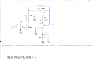
"The input current to this op amp in the below circuit is nearly equal to the source current--this shouldn't be the case given that the input impedance is 10^13 ohms. Is the model bad? I am using the texas instruments op-amp library in PSpice(with attachments)"

I would like to ask your confirmation on this as we've no PSpice tool on our current engagement to support this query. Based on his circuit, it seems that he wanted to configure an AC integrator op-amp. But because he directly connected the AC signal to inverting input, it looks like they are virtually connected with grounded non-inverting pins.

Any thoughts and confirmation on this?

Regards,
Archie A.


Transimpedance Amp Pspice Files.zip

  • Actually, I am not really sure how did they measure the current on this, the graph they showed seems like for AC signal generated only.

    I believe measuring the input current must be done by putting the ammeter in series with the input pin.

    I'm not familiar with PSpice and its environment, thus need your assistance on this.

    Thanks for your support.

    Regards,
    Archie A.

  • Hello Archie,

    I am not able to see the details of the OPA145 transimpedance circuit because the image is way too small. However, since your concern is about the OPA145 simulation model's input bias current I set up a simple circuit and tested them using both TINA-TI and PSpice for TI. I obtained the same DC input bias current (Ib) and voltage offset for the simple buffer using both simulators. The inverting input shows an Ib close to 1 fA, and the non-inverting Ib about 500 fA. These are less than the +/-2 pA typical listed in the datasheet Electrical Characteristics table. It looks like the OPA145 Ib currents are okay.

    If you can provide a larger, more visible schematic for the circuit it would be easier for us to see what your intentions are for it.

    Regards, Thomas

    Precision Amplifiers Applications Engineering

  • Hi Thomas,

    Thanks for this very detailed info.

    Regarding the attachment provided, I guess by clicking the snapshot, there would be an option from its upper left corner to zoom in and drag it to the right to clearly view the circuit.

    Thanks for your support.

    Regards,
    Archie A.

  • Hello Archie,

    I was looking at the small image in the post and not the zip file. Once I opened the file I could then see the image much better.

    There is a problem with the way this transimpedance amplifier is being implemented (TIA). In actually, the circuit is being set up as a voltage amplifier stage that is essentially operating open loop. The TIA 10 Meg resistor is acting acting as the feedback resistor, and the 0.3 Ohm shunt resistor as the input resistor in a voltage amplifier. The noise gain observed from the non-inverting amplifier is [1 + (Rf/Ri)] = 1 + 10e6/0.3, or 33 million V/V which is larger than the OPA145 open loop gain (Aol) itself.

    The typical voltage offset of the OPA145 is +/-40 uV. Multiplying 40 uV times 33 million will try to put the output voltage at 1333 V. The output will slam to its swing rail which will be close to one of the 6 V supply limits. Once the op amp's output is forced to a swing limit normal op amp operation is lost and all bets are off in terms of what the op amp will do electrically. Since the simulation models are designed for linear operation forcing them into non-linear operation results are not reliable.

    Since the input source can provide a peak current of 10 mA, and there is a 0.3 Ohm shunt resistor, a maximum peak voltage of 3 mV can be obtained. If the voltage needs to increased to a usable level simply connect the OPA145 as a voltage amplifier, not a TIA. If the stage is set up for a gain of 100 V/V, then the output would swing 300 mV off its quiescent point when the 0.3 mV voltage is present.

    If the customer has some other idea in mind what they need to do then we may be able to provide some advice.

    Regards, Thomas

    Precision Amplifiers Applications Engineering

  • Hello Thomas,

    Thanks for your detailed response.

    Does the circuit below would suffice?

    Thank you.

    Regards,
    Archie A.

  • Hi Archie,

    Unfortunately, this still isn't going to work correctly. The 10 uA source current would normally flow through the TIA gain set resistor, the 10 Meg feedback resistor. Ten microamps flowing through a 10 Meg resistor would require the OPA145 output to swing to 100 V, which is clearly outside the output range of the op amp. If the feedback resistor is reduced by a few orders of magnitude the output will then be within the linear swing range with a peak input current of 10 uA.

    If you can provide us more information about what you are trying to do with the circuit we should be able to provide some advise.

    Regards, Thomas

    Precision Amplifiers Applications Engineering

  • Hello Thomas,

    That's also I am thinking though.

    The current graph he is showing is also that of the Rs (3M ~ like open circuit to me as current  signal is too small also) and not the input bias current he is referring to. I am still waiting for the response from the client regarding his concern.

    Thanks for your great support.

    Regards,
    Archie A.