This thread has been locked.

If you have a related question, please click the "Ask a related question" button in the top right corner. The newly created question will be automatically linked to this question.

OPA196: Question regarding choice of resistors for differential op amp configuration.

Part Number: OPA196
Other Parts Discussed in Thread: ALP

Hello, I designed a circuit that takes the output of a hall and amplified that output using the op amp given in the description. However I am finding that the output voltage is lower than what I expected. I will provide more detail below.

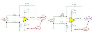
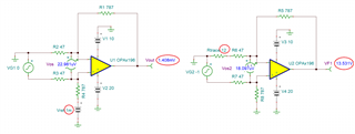
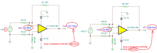
The hall sensor I am using has a differential output that goes from 0-0.6V, so I used this op amp in a differential configuration to obtain an output that goes from 0-10V. Thus, requiring a gain of ~16.67 V/V. The resistor values I chose were 47 ohms and 866 ohms. They were all tested and very close to their advertised value. I am wondering if I am expecting some loading effect because my resistor values are too small? If so, what resistor values do you recommend?

  • Hi William,

    Thanks for your post. Can you please attach a schematic? You may also use our TINA spice simulator tool to build this schematic. I have attached a file with the OPA196 that you can edit with your circuit specifications. 

    TINA simulator download: https://www.ti.com/tool/TINA-TI 

    OPA196 model: attached

    OPA196.TSC

  • I'm sorry I only can provide a screenshot at the moment. I hope this is sufficient. Please ignore the bottom right.

    .

  • Hello William,

    You mention the gain is somewhat off of what is expected. Can you provide us some idea what level of gain error your are seeing? Does it occur over the entire output voltage range, or just near the ends of the output range? Is the Hall Effect sensor input an AC signal or DC level? If you have the measured values for the gain set resistors that would provide us an idea what gain error would be caused by resistor tolerance. 

    I do think that the resistors that you have selected to use around the OPA196 in the Hall Effect sensor circuit are unusually low in value. In particular the R4, 787-Ohm and R3, 47-Ohm resistors around U5 that may be involved in sinking/sourcing current to the U1 Hall Effect sensor's Vref pin. If the U5 output swings 10 V and the Vref pin does sink/source the current might be limiting the OPA196 output swing range. A quick check of things would be to increase the R4 and R3 resistors specifically by 10x, or even R1 - R5 by 10x, and see what happens to the gain error.

    Regards, Thomas

    Precision Amplifiers Applications Engineering

  • Hi Thomas,

    The gain I was expecting was ~16.8 V/V, however, I am seeing the gain around 13 V/V. It does appear that the output is still linear over the whole range, but the gain is much lower.

    The hall sensor is receiving a DC signal and has a DC output.

    The resistors I am using have a 1% tolerance so they are very close to the values should be. I had to increase RV1 so the output of the op amp would be zero when the hall sensor had no current through it. However, with the actual resistor values I have, RV1 should not have had to increase to the extent I increased it to (~59 ohms).

    Thank you,

    William

  • Hi William,

    The fact that the output remains linear over the full range is a good indication that the OPA196 is behaving as it should. 

    So RV1 in conjunction with R5 is establishes a voltage divider that affects the U1 sensor's output level being applied to U5's pin 3 input. I assume that you are measuring the voltages at U5's pin 3 input, and pin 1 output? Then, calculating the gain based on:

    Vo(pin 1) = V(pin 3) (1 + R4/R3)

    If by chance you aren't taking into account the voltage divider's (< 1 V/V) gain, then the overall gain will be off.

    Regards, Thomas

    Precision Amplifiers Applications Engineering

  • Hi Thomas,

    I'm sorry I'm a little confuesd. I'm measuring the gain by taking Vo/Vin of the op amp. I see what you are saying with the voltage divider analysis, but I don't necessarily see how that should be different than the ideal gain of a differential amp ( Vo = (Vout,sens - Vref) * R4/R3 ).

    Best,

    William

  • Hi William,

    We are probably thinking the same thing, but explaining it differently. The way I see it the U5 Vout is:

    Vout(U5) = Verf(U1) (-R4/R3) + Vout(U1) [R5/(R5+RV1)] [1+(R4/R3)]

    Since RV1 is adjustable the gain through the two input paths can be different except for when RV1 = R3.

    Do you agree?

    Thomas

    Precision Amplifiers Applications Engineering

  • Hi Thomas,

    I completely agree with what you are saying. I just think it is strange that I had to change RV1 so much when the other resistors were accurate. If you plug in the excat values of the resistors, RV1 should be 47.9. Perhaps poor soldering is causing error. I did notice that when I adjust RV1 to where it should be the gain is fairly accurate but then my ouput isn't zerod when it should be.

    At any rate, do you think the small resistors are causing an issue as the output impedance of the op amp is 700 ohms (if I am reading that correctly)? My thinking is that the ouput impedance is similar in value to my resistors its making a significant impact in my overall resistance.

    Best,

    William

  • Hi William,

    The OPA196 Electrical Characteristics table as you have noted lists the Open-loop Output Impedance Zo, as 700 Ohms at 1 MHz. Figure 19, the Open-Loop Output Impedance vs Frequency graph in the Typical Characteristics curves section shows that over much of the OPA196 frequency range that the Zo is closer to 1500 Ohms, but that really isn't a concern. That is because it is the Closed-loop Zo will be much lower as will be demonstrated. Zo is very important for AC performance and stability analysis. That is why the graph is included in the datasheet and why Zo is built into our op amp simulation models.

    The Closed-loop output impedance which I like to designate Zcl is directly related to the Open-loop gain (Aol) and the Closed-loop gain slected at the frequency of interest. The closed-loop gain (Acl) is the noise gain (1 + Rf/Ri) as established by the selected feedback and input resistors. Another other gain term of interest is the Loop gain (Alp), which is the difference between Aol and Acl. Then the closed-loop output impedance can be approximated from, Zcl = Zo / Alp.

    For example, using a frequency of 1 kHz the OPA196 Aol is about 70 dB (3162 V/V) as seen in datasheet Figure 2. Zo is about 1500 Ohms from Figure 19. For this example we will use a closed loop noise gain of 17 V/V (24.6 db). Then Zo can be calculated:

    Alp = Aol - Acl = 70 dB - 24.6 dB = 45.4 dB (186 V/V)

    Zcl = Zo / Alp = 1500 Ohms / 186 V/V = 8.0 Ohms

    So the closed-loop output impedance (Zcl) is significantly lower than the open-loop output impedance (Zo).

    I would try increasing the resistors by 10x and see what outcome you obtain.

    Regards, Thomas

    Precision Amplifiers Applications Engineering

  • Adding to Tom's comments, what you get in terms of gains is exactly what you should see - see below.

    I believe the error comes either because your reference driver has offset (e.g. 1mV - see below on the left) or of due to mismatch in trace resistance (e.g. 12 ohm - see below on the right).  Of course, to Tom"s point using small resistors increases the current in each diff amp leg and thus exaggerates the problem.

    Changing gain will change the output simply because of the change of gain amplifying the offset. BUT you should not do this-offset must be calibrated out.

    I believe you have never told us what offset you actually see.