This thread has been locked.

If you have a related question, please click the "Ask a related question" button in the top right corner. The newly created question will be automatically linked to this question.

OPA564: Thermal protection

Part Number: OPA564
Other Parts Discussed in Thread: TINA-TI

Hi everyone,

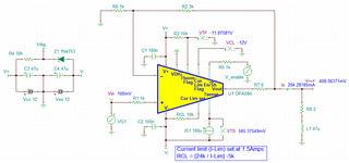
I'm using the OPA564 to feed an inductive load of 2 ohms and 47µH at 100 kHz.

My input signal is a sin wave with a 700mV amplitude. I have a gain of about 4 so I have an output of about 3V to feed my load.

At 100 kHz, my load exhibits about 30 ohms of inductive reactance. That means that the maximum current travelling through the coil should be 100mA.

But I have a problem : the power supply indicates that more than 300 mA are delivered to the circuit.

A precision : I did not make a thermal pad. It was just a test for the OPA564 (just to check the good functionning of my circuit). I was thinking that with 100mA, the thermal problematics would not appear, but the thermal protection goes on and off in a cyclic way.

So the question is : do you have an idea why the current is too high related to what was expected? Could it be due to the absence of thermal pad?

Thank you in advance

Sylvain

  • Hi Sylvain,

    At 100 kHz, my load exhibits about 30 ohms of inductive reactance. That means that the maximum current travelling through the coil should be 100mA.

    The load impedance should be 2Ω + 2*pi*100kHz*47uH = 31.5Ω @100kHz. If the input is +/1Vpp, then the output current is approx. 140mA. (4V/31.5Ω @100kHz +  8.6mA at DC). 

    If your input sine wave (100kHz) has DC offset, then the circuit output current will be higher as shown in the example below. My guess is that this is likely the case. 

    Could it be due to the absence of thermal pad?

    Without thermal pad soldered to a heat dissipated surface, the junction temperature may operate at an elevated temperature, which it may limit the output current and behaves unexpectedly. Is the top surface of the op amp hot when you tough the top surface?

    Enclosed is the OPA564's simulation. Please let me know if you have issues. It should be able to drive it if the load is 2Ω + 47uH, based on the simulation. 

    OPA564 Driving Inductor-A 11102021.TSC

    Best,

    Raymond  

  • Hi Raymond,

    Thank you for your answer.

    I'm not sure to understand how you know the DC current to add. Could you explain, please?

    Then, I don't exactly see the difference between the two figures : what are the blue values? Are they the values that you defined?

    With these answers I will be able to understand correctly your answer.

    Thank you very much,

    Sylvain

  • Hi Sylvain,

    what are the blue values? Are they the values that you defined?

    Are you referring to the values boxed in red? If this is the case, please see the reply below.

    If you are able to run TINA-TI simulation,  you select Under DC analysis --> Calculate Nodal Voltages option, you will get the DC operating conditions from the simulation. With 100mV DC offset at the input VG1, the output voltage is measured 4*100mV + Voffset. or 408.6mV, and the source current is 204mA for the give load (since inductor is a short at DC and 408.6mV/2Ω = 204.3mA). 

    When you are operating at 100kHz, there are DC and AC current components at the op amp's output. I am speculating that your input sine signal may have DC bias component and that is why that you are observing higher output current. 

    If you have additional questions, please let me know. 

    Best,

    Raymond

  • Thank you Raymond. I added a capacitor in series with the coil, at the output of the OPA, and it works fine now.

    Thank you,

    Sylvain