Hi,
Good Day. I have a customer who is working with operational amplifier. Please see below his query for you reference. Thank you very much.
I bought the mentioned IC. I have a problem with its behavior.
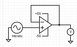
Basically I'm trying to use the OpAmp as a Follower. So the input signal is connected to the non-inverting input. The output of the OpAmp is connected to the inverting input. The supply Rails are ranging from -5V to +5V.
The input signal is a sinusoidal signal with 100kHz generated by a function generator.
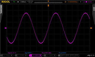
Considering this Setup I observed, that the output signal is distorted starting at around +2.4V. It seems to only affect the positive halfwave of the output signal.
What is happening? Because if I use the OpAmp not as a follower, but as an inverting amplifier the problem goes away.
That's the schematic. I put the IC on a breakout-board.
I attached some pictures from the oscilloscope. The violet trace is the input signal and the blue one is the output.