This thread has been locked.

If you have a related question, please click the "Ask a related question" button in the top right corner. The newly created question will be automatically linked to this question.

THS3491: TINA-TI Simulation - Convergence Problem Error

Part Number: THS3491
Other Parts Discussed in Thread: TINA-TI, BUF634A, THS3121, OPA564,

Hello,

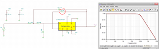
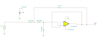
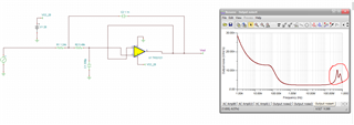
I am simulating a low pass filter using the THS3591 OpAmp using TINA-TI. When I simulate the filter results with the Transient Analysis tool, I run into an Error stating, "Convergence problem. Check the analysis parameters!"


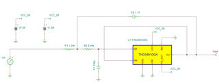
(Here is an image of my circuit, but for some reason I can't insert it with better quality). 

How do I resolve this error in TINA-TI or modify this circuit to act as designed? Previous analysis was done using the AC Transfer Characteristics tool which generated a desirable Bode Plot. 

Thank you,

John

  • OpAmp_Sim.TSC

    Attached is my TINA file for reference

  • This simulation is telling you this circuit will be unstable, never ever use cap feedback with a CFA device. 

  • Hello John,

       Also to add onto Michael's suggestion, CFAs are used in a negative feedback configuration and need a feedback resistor in order to preserve the stability of the amplifier. More information can be found at this blog post. You could implement a low pass filter application via RC filter at output of the amplifier. 

    Thank you,
    Sima 

  • Yes Siima, I should have expanded the ckt to see it was an SKF which can work - but, it has no feedback R so will oscillate. Also, running single supply is possible but here I got it to work fine recentering on ground and changing the source to remove its DC level. So possible, but not sure why to use a 900MHz CFA for this 100kHz filter. 

    THS3491 SKF.TSC

  • Michael,

    The primary reason I'm using this OpAmp is for its current driving capabilities. This application requires >400 mA driving current, and I thought that this component best fit my application needs.

    It sounds like if I want to make this circuit work, I need to either find a new part or add a feedback resister. How might this feedback resister affect the filter's performance?

    Thank you,

    John

  • Well that is a good reason, but it is kind of pricey for just that. If you just need a unity gain in the amp, maybe the BUF634A would be enough. If 100kHz is your target Fo, 10Mhz closed loop BW in the amp is plenty. 

    The THS3121 is another high output CFA that is cheaper. 

    Anyway, the feedback R sets the phase margin for CFA to get the rated closed loop BW. It is required for CFA. It does not effect the filter any more than any closed loop BW consideration might in an SKF. 

  • And before I leave this, if 24V total supply is enough, the OPA564 has plenty of output current and the 17MHz is plenty for your filter. 

    To maybe pursue a cost reduced approach, perhaps a lower output 36V VFA with about 10MHz GBP with two BUF634A in parallel inside the loop would fill the bill. There are some compensation challenges there, but not insurmountable. 

  • Michael,

    Unfortunately, a 24V supply is too small for us. We need to be able to output 0 to 25 Vpp and will be supplying the OpAmp with a 28V supply. 

    I'll take a look into using BUF634As rather than the TPS3491.

    Thank you,

    John

  • Make sure you include the output headroom requirements for the power stage while providing that current - we call that the claw curve and is in most new datasheets. Headroom (or drop from supply) increases with output current as an IR term. 

  • Thanks for the heads up. For this application a 28V supply is the largest we can obtain, so if I redesign the filter, I'll focus on components that minimize the slope of the claw curve. 

  • 25Vpp on 28V supply with 400mA out is likely not possible. You also have an input headroom issue using the SKF in unity gain, either use gain in the amp or go MFB which then definitely requires a VFA overall op amp

  • Michael,

    I repeated the simulation using the THS3121 Spice Macro in TINA-TI and this time was able to achieve a steady transient response, even without a feedback capacitor. This OpAmp also has desirable output current capabilities. I have a couple more questions for you.

    1. Is TINA-TI capable of simulating the claw curve? If so, would I just put a loading resistor between the output and ground to simulate?

    2. Would it be good practice to insert a feedback resistor despite the simulation working? Is there a specific value of feedback resistor that I need to remain above?

    THS3121_SIM.TSC

    Thank you,

    John

  • Well it may or may not have that in the model, but the specs tell you it won't work - here, 50ohm load can swing 12.5V with 15V supplies, that is 2.5V headroom. Your requirements suggest a 1.5V headroom max under load - even the THS3491 will not do that. recently discussed that here, 

    e2e.ti.com/.../ths3491-max-output-current

    You have not apparently used a CFA before - the sim might be working but if you look out far enought a noise spike in the output indicates instability - if you don't mind a 500Mhz oscillation no feedback R is fine, otherwise use the recommended value in the datasheet - for gain of 1, that is 806ohms - that is chosen to give 60deg phase margin gain of 1 with stated load. 

  • I have not used a CFA before which is probably why I'm asking so many questions. This last explanation clears up most of it for me. 

    Thank you!