This thread has been locked.

If you have a related question, please click the "Ask a related question" button in the top right corner. The newly created question will be automatically linked to this question.

ALM2403-Q1: Stability Margin

Part Number: ALM2403-Q1
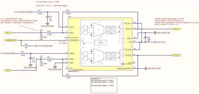
Other Parts Discussed in Thread: ALM2402F-Q1

Hi Team, seeking your assistance.

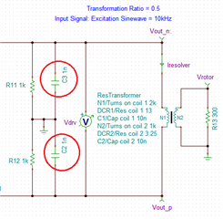
Output load = 1nF (EMC cap)

(Other output load = resolver)

gain = -10

What is the best method/tool to verify the stability margin ?

and decide if a series resistor is need.

Thank you in advance.

-Mark

  • Hi Mark,

    What is the best method/tool to verify the stability margin ?

    Tina_TI will perform the BW and phase margin simulation nicely.  

    ALM2403-Q1 should be able to drive 1nf capacitive load without any stability issue, but I will check it out anyway.

    Please send me the resolver driving circuit and I will perform a check. By the way, please provide  me with resolver's LRC parameters, excitation frequency, driving amplitude, transformer ratio and other relevant important parameters. It will be good to provide me with resolver current driving information and heat dissipation figures, say under a worst case scenario. 

    If this is proprietary design and you do not want send over E2E forum, please send the information to my internal email. 

    Best,

    Raymond

  • Hi Raymond,


    They are looking at ALM2403QPWPRQ1 to replace ALM2402F)
    (power supply is 10V)
    There is also a 1nF cap between each output and ground.
    The resolver is 13ohm in series with 2.15mH.
    Excitation frequency is 10kHz. Input is sine wave.
    The level between EXC POS and EXC NEG is about 14.4Vp-p

    BTW, do you have any other concern about replacing ALM2402F with ALM2403

    /resized-image/__size/640x480/__key/communityserver-discussions-components-files/14/6787.Capture.JPG

    Thank you.

    -Mark

  • Hi Mark,

    Could you resend a higher resolution image? I am unable to make out all the figures and comments from the image (I am trying to send you the simulation as the application is captured). 

    There is also a 1nF cap between each output and ground.

    Yes, 1nf will be ok. In my prior simulation for a customer, I had 10nf that is connected to ground, shown in red circle.  

    They are looking at ALM2403QPWPRQ1 to replace ALM2402F:

    May I ask what features are you looking for in ALM2403-Q1 vs. ALM2402F-Q1? It mentioned that the application is a single supply voltage of 10V. I do not see that there is advantage to change from ALM2402F-Q1 over ALM2403-Q1.

    If you want to maximize the Vout swing under Vs = 10Vdc, ALM2402F-Q1 has the advantages.  ALM2403-Q1 has high supply voltage rail and can withstand overvoltage up to 24-26Vdc. ALM2402F-Q1 has the absolute maximum supply voltage rated up to 18Vdc. 

    Best,

    Raymond

  • Hi Mark,

    I am gong to close this inquiry. If you have additional questions, you may re-open the thread or recreate a new one via E2E forum. 

    Best,

    Raymond