This thread has been locked.

If you have a related question, please click the "Ask a related question" button in the top right corner. The newly created question will be automatically linked to this question.

INA237: register read value doesnot match the datasheet

Part Number: INA237
Other Parts Discussed in Thread: INA226, INA238

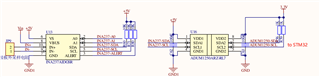
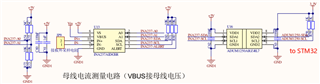
Hello,I  have tried  two types of INA237。they are  INA237AIDGSR and   INA237AQDGSRQ1,and  I connected  it  with  STM32, below  is  the  schematic  

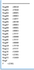
And  I  found  it was  really weird  that  the register value  didnot  match  the  datasheet,below  is  the register  value  I  had  read。

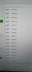
However, I also  tried  to  use INA226 to replace the INA237(pin-pin),and ramained  the code and schematic unchanged,then I can read the right value 。

I dont know why。。。。

  • Hello,

    Your circuit seems to be correctly configured. I am assuming you are just reading from the registers before you have set anything and are getting these values? 

    I have a couple of questions to ask to better help you.

    What is A0 and A1 connected to? Are you using the correct INA address for the A0 and A1 configuration?

    What speed are you running the I2C?

    Is it possible to see the I2C communication scope shot?

    Regards,

    Castrense

  • 1.yes,I didnot set anything before I read the register,and after that  I also tried to write  new values to some RW registers like CONFIG, SHUNT_CAL, ADC_ CONFIG,but the value can not even be changed。

    2.A0,A1 are both pull down to the GND.Here it is。

    3.I2C speed was 100k,standard mode。

    4.yes,but it might take me some other time,I will upload the scope shot later。

  • Hello,

    I do not see a problem with the circuit. My only concern from the discussion above is you are not communicating with the INA. Since you have A0 and A1 as GND the INA237 address should be 1000000. 

    Lets also make sure you are initiating a read correctly. First you must set a register pointer to point to the register you would like to read, then you can read the register.

    Below are some screenshots of the datasheet that state how to perform these actions. 

    Fig1.

    Fig2.

    As you can see to set the register pointer you must first send a start by pulling SDA low while SCL is high then send the address of the INA237 (1000000) followed by a write so the first byte of communication by the master should be 10000000, then the INA should ACK. The second byte must be the address of the register you would like to read in the case of the configuration register it would be 0x00 or 00000000. Then send a stop condition by letting go of SDA and SCL. 

    The next part is the part we get the data from that register. First send a start then the address of the INA followed by a read (10000001). Then the INA will ACK and will read back the first byte of data (MSB), there should be an ACK by the master. Then the second byte (LSB) will be sent by the INA and a ACK can be sent by the master or not. This will be the end of the communication to read one register. 

    You will also need to pay attention to the sections 6.6 and 6.7 of the INA237's datasheet to make sure you are satisfying all the I2C communication timings. 

    I will be waiting for the scope shots. 

    Regards,

    Castrense

  • Hi, the scope shot  of  INA237 is like this

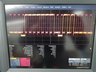
     ,yellow line is SDA,red is SCL,the test point was on the pin.2 and pin.3 of ADUM1250。

    we have tried 3 different  chips: INA226,INA237,INA238,and the scope shots are almost the same as above。

    Here is  test results  and some our own analysis:

    First we found that the when the MCU tried to send a low level, after the signal pass through the ADUM1250,the low level wasnt really low ,but a 0.8-1V stage(as the picture shows)。And when the slave(INA237)ACK,the low level can be pulled down to nearly 0。Comparing  the two datasheets of INA237 and INA226 , we found that the VIL of  two chips  are  different,for 226,the VIL is 0.3*Vs(page.6 in datasheet),which in our design is 0.3*5=1.5V;but for 237,the VIL is 0.4V。So ,at that time ,we guessed  it was the Low Level too high that caused INA237 worked abnormally。

    Then ,we  replaced the R60 and R71 from 10kΩ to 20k Ω,test again,the waveform  changed little ,and the register read value were wrong as expected。


    But,then we replaced the INA237 with INA238(which has similar electrical characteristics with INA237),kept  the 20kΩ pullup resistor,we found that the resistor read value was completely right ,like below。

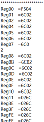
     at this time ,the scope shots were  almost the same ,the 0.8-1V stage of  low level  still existed,and also exceed the VIL threshold of  INA238。
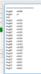
    then ,we replaced the pullup resistor with 4.7kΩ,test again,the waveform kept unchanged, but the register read value was wrong

     ,then,replaced the pullup resistor with 10kΩ,test again,register read value was wrong。Replaced the pullup resistor back to 20kΩ,test again,register read value was right。

    So, here is our test results table:

    CHIP 4.7kΩ pull up 10kΩ pull up 20KΩ pull up
    INA226 register read value right register read value right register read value right
    INA237 register read value wrong register read value wrong register read value wrong
    INA238 register read value wrong register read value wrong register read value right

    And there was a very interesting phenomenon:I made two jumper wire from he pin.2 and pin.3 of ADUM1250,so it was convenient  for  our probe clip to test the signal。When we test INA238,if we dont connect the probe with the jumper wire,the read value was right ,but if I touch the wire with my hand,the register read value was wrong。

    So,I am totally confused:

    1. why the different pull-up resistor can cause different read result?

    2. INA237 and INA238 have  the same electrical characteristic of  VIL,why 238 can  work with 20kΩ pull up,but 237 cannot。

    3. how to explain  that once I touch the jumper wire ,the read value changes。 

    Best Regards!

  • Hello,

    The problem seems to be caused by the the low logic level voltage that the ADUM can do (as you mentioned). The INA 237 must have a low logic level voltage of max .4V so the low of side 1 of the ADUM being 900mV is too high. 

    1, As far as why different pull-up resistors cause different behaviors the loading on the ADUM will cause a different sourcing characteristics. 

    2, This can happen because of the part variation.

    3, By touching the wires you are loading the I2C lines.

    If you have any other questions please reply

    Regards,

    Castrense