Other Parts Discussed in Thread: LMC662, LMC6061, LMC6081, LMC660
Dear Team,
May I know the I/P resistance of TLV9102.
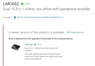
In TI website I can see that TLV9102 is a replacement for LMC662.
LMC 662 has I/P resistance grater than 1T ohm

Regards
HARI
This thread has been locked.
If you have a related question, please click the "Ask a related question" button in the top right corner. The newly created question will be automatically linked to this question.
Hi Hari,
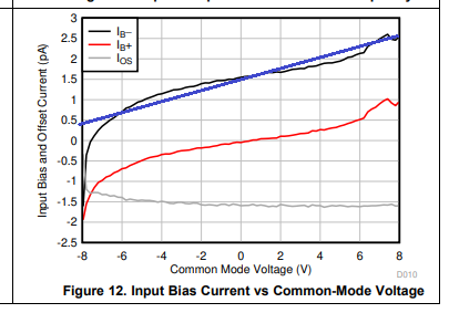
figure 12 of datasheet of TLV9102 shows that the typical input resistance at room temperature is about (8V - (-8V)) / (2.5p-0.5p) = 8T. See the blue line:

But when you carefully compare both datasheets you will notice that the input bias currents of LMC662 are much lower compared to the TLV9102. The LMC662 even shows a maximum input current specification at the temperature extremes.
Kai
Hi Kai,
Thank you very much.
May I know, why only the positive part of the input bias current is considered (2.5p-0.5p).
Why IB- curve is considered here.
(2.5p-0.5p) this region is almost linear. Because of this, you considered the range of (2.5p-0.5p)
Regards
HARI
Hello Hari,
If input bias current is critical then TLV9102 is not a valid replacement. TLV9102 has some advantages, but input current is not one of them.
Hi Ron,
Thank you very much.
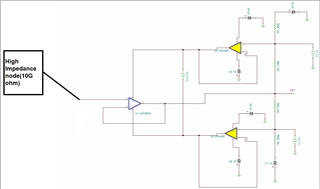
This opamp is a part of my ASIC evaluation Board. The ASIC has a charge pump(this charge pump is used to Power MEMS) which has a high I/P impedance of 10G ohm. Below is my Circuit. I choose LMC662 because it has an I/P impedance greater than 1T ohm.

Regards
HARI
You can simply continue to use the LMC662.
If you want to choose another one: here is a search for 15 V op amps with at most 3 mV offset voltage and at most 4 pA input bias current: www.ti.com/amplifier-circuit/op-amps/products.html#p1261max=15;180&p2max=0.002;3&p3247max=0.02;4. The LMC6081 has even higher input impedance; the LMC6061 saves power with lower speed.
Hi Kai,
This circuit is tested and working fine.
I can see a shortage of LMC662. As a backup plan, I am looking for an alternate P/N.
Kai, I have one more question.
The above circuit works properly from -40 to 85 Deg.
May I know is there any way to implement the above logic so that it can work from -40 to 150Deg.
Regards
HARI
Hari,
High temperature is the worst thing when low input bias current is desired.
Here is a search for dual op amps in SOIC package, sorted by input bias current. Device starting with LMC6 or LMP are more likely to be compatible.
https://www.ti.com/amplifier-circuit/op-amps/products.html#p480=2;2&sort=p3247max;asc
Hi Ron,
Thank you very much . I will look into it.
May I know you have any suggestions/Other methods to measure voltage from a High Impedance node.
I used bootstrapping because my charge pump voltage is 36V.
I am looking for some other method that can work properly from -40Deg to 150Deg.
Regards
HARI
Hi Hari,
I don't think that the output of this charge pump is higher impedant or shows less leakage current than the input of an ultra low input current OPAmp like the LMC662. Also, the MEMS will shurely draw much more current than the input current of LMC662.
Kai
Hari,
Do you need a device that works up to 150C or has specifications up to 150C?
150C is very uncommon so very few choices. 125C is very common, but many would be larger input current.
Have you tried LMC662 at 150C?
Hi Hari,
if I were you, I would just make tests with the LMC660 at elevated temperatures. Otherwise this discussion becomes too academic.
Have the MEMS and the charge pump also connected to the LMC660 and I'm sure you will see that the leakage current of MEMS and charge pump will heavily dominate the input leakage current of LMC660.
Kai
May I know the difference between "a device that works up to 150C or has specifications up to 150C".
If the data sheet says that the op amp works up to 150C, that means it will work per specifications in the data sheet.
If device works up to 150C in reality (although not stated in data sheet) then it could work (most of the time and with a shortened life). The key point is that any warranty will be effectively void and all the risk is yours.
Are all the other devices in this application rated to 150C?
The main reason I asked about LMC662 at 150C was to get baseline performance to compare against a true 150C device. Along the same thinking, does your application work at 150C with or without reading the voltage?
Hi Ron,
Thank you very much.
Since the ASIC needs to be tested up to 150Deg,I decided to go with 2 Boards.
One board contains only the seat for mounting ASIC and its related connectors. This board will be sitting inside the oven.
The other board contains signal processing, measurement circuit, etc. This will be sitting outside the oven.
I am only concerned with this high impedance section. I am planning to provide guarding for that trace.
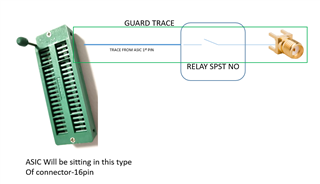
The signal chain for the high impedance node, inside the Board which is sitting in the oven, is given below.

Do I need to use a guard trace or can I provide no copper area near the trace as shown below

Regards
HARI
Hi Hari,
take care, every relay needs a minimum current to make a proper contact. But the input bias current of LMC660 is way too low and by this you force the relay contacts to perform "dry switching". Only massive gold contacts resting in an inert gas atmosphere can perform "dry switching".
Also keep in mind, that many ovens suffer from control fluctuations of temperature resulting in peak temperatures way higher than 150°C.
Kai
Kai,
Can you provide a reference for "every relay needs a minimum current to make a proper contact"? This is the first I time have heard this. My research for this phrase resulted in questions about minimum coil current. Wet an dry contacts search was also not helpful.
If current is fA then a closed relay with millions of ohms contact resistance would still measure fine.
Do I need to use a guard trace or can I provide no copper area near the trace as shown below
A guard is needed to stop leakage. The SMA connector should also be connected to guard.
Here is the firs part of a three part article that is very informative. EDN - Design femtoampere circuits with low leakage, part 1 -
Hari,
The guard should surround the ASCI trace for the entire journey from ACIC to LMC662 input pin. The guard voltage should be a close to ACIC pin voltage. So the cable (board A to board B) has ASIC in center of coax cable and Guard on outer conductor of coax cable.
You may want to consider using a triaxial cable. Inner is ASIC signal, middle is guard and outer is ground.
Hi Ron,
here are two examples:
Harmony Electromechanical Relays_RSL1AB4ND.pdf
I have lots of other data but unfortunately only in German.
Kai
Hi Kay,
Below is my relay P/N
https://www.cotorelay.com/wp-content/uploads/2014/09/9011_series_reed_relay_datasheet.pdf
May I know what you mean by "minimum current to make a proper contact".
I hope you are telling me about coil current. Please correct me if I am wrong.
Or you are telling about minimum switching current.
Regards
HARI
Hi Hari,
no it's not the coil current what I mean, it's the current through the switching contacts.
Contacts not sitting in an inert gas atmosphere suffer from oxidation and corrosion by sulfur dioxide. This results in a thin isolation layer on the contacts. A minimum switching voltage and switching current is needed to "free-burn" the contacts then, every time you close the contacts. Think of a microscopical arc.
When you use massive gold contacts in an inert gas atmosphere, on the other hand, this minimum switching voltage and switching current needed to make a contact is very very small. Such a relay would allow so called "dry switching".
When two relay contacts come in close contact and a current is flowing between these contacts, a very sophisticated physical phenomen takes place, the quantum mechanical tunnel effect. In the best case, if everything works well and no oxid layer have to be "pierced", the ohmic law applies. But when you force oxidized contacts to perform "dry switching" while an ioslation barrier exists between the contacts, very weird things can happen. It's not just that the contacts become high ohmic, it's much more complex. Threshold levels and hysteresis for the switching voltage and switching current develop which can result in a "clattering" behaviour where the contacts are peridically making (bad) contact or fully isolate.
Usually, the problems rise with increased age of relay contacts.
Kai
Hi Kai,
Thank you.
This is very informative.
Many relay vendors do not specify this spec. Below are the datasheets of two relays that I am using. There is no such info in contat spec.
https://omronfs.omron.com/en_US/ecb/products/pdf/en-g5nb.pdf
https://omronfs.omron.com/en_US/ecb/products/pdf/en-g5ca.pdf
Regards
HARI
Hi Hari,
we are steadily progressing towards a digital world and the "good old" analogue knowledge and experience gets more and more lost.
Your relays seem to have "all-purpose" Ag-alloy contacts which are not resting in an inert gas atmosphere.
Why using a relay at all at this point? You could take a simple connector with gold contacts.
Kai
Hi Hari,
you can still have the (many) LMC660 sitting outside
Another option is to mount the LMC660 close to the ASIC and to cool the LMC660 by an air stream. Install the LMC660 in a small thermally isolating enclosure and connect two pipes to the enclosure, one for the fresh air and another for the outgoing air. There are cheap pumps available to generate the cooling air stream. We have done this many times.
Kai