This thread has been locked.

If you have a related question, please click the "Ask a related question" button in the top right corner. The newly created question will be automatically linked to this question.

Using INA213 to measure low currents

Other Parts Discussed in Thread: INA110, INA131, MSP430F2112, PGA204, PGA280, INA159, INA213, INA200

Hi guys,

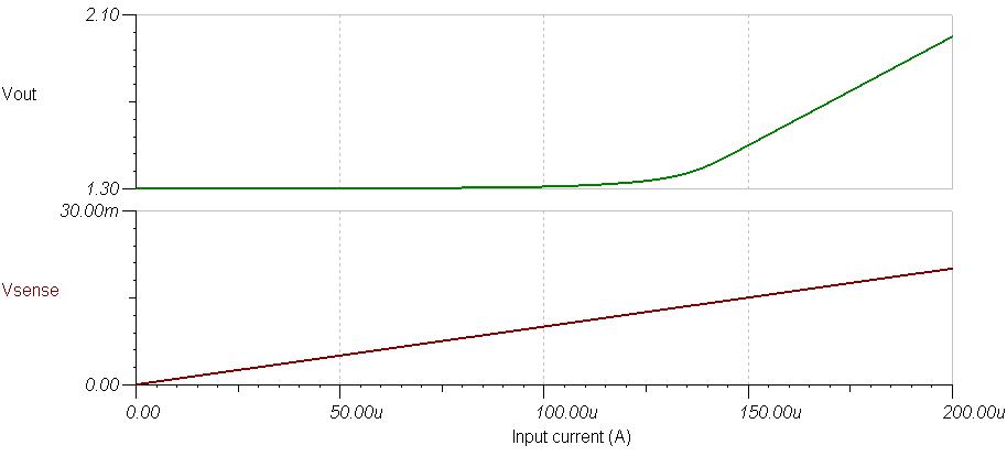
I'm working on the design of a circuit to measure the current consumption of MSP430. Based on the specification of INA21x shunt monitors, these amplify accurately sense voltage of down to 10 mV. But according to TINA simulation results, INA21x suck with low currents, due to high input bias currents (I think) but this is not mentioned in the data sheet as far as I know.

I attached my circuit for your review. Unfortunately the TINA .tsc simulation file could not be accepted. The circuit has to cover the wide current range from 1uA to 100mA. I though to use the 1k resistor for currents lower than 50uA, then 1000ohm//20ohm for currents between 50uA and 2,5mA... and for higher currents I thout to measure Vsense directly with the ADC. I set V+ of the INA to 2,5V because the ref voltage of my ADC is 2,5 V

The resistor R6 and the source VG1 are ther just to siumlate the dynamic behavior of the processor.

Could you please help me answer to this questions:

1) why does the INA not work for low currents?

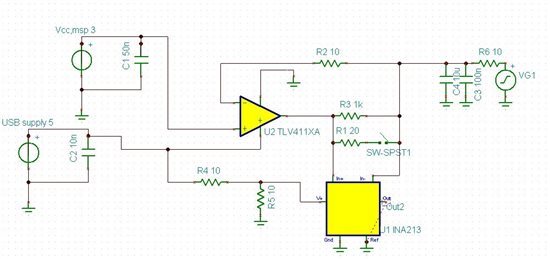
2) what do you think about my circuit, what can I improve in it to get accurate results?

Thnx

  • Hello MSP430-Beginner,


    Our dedicated current shunt monitors are designed for measuring high-currents with common-mode voltages that typically extend beyond the supply voltage range of the device.  They typically have uAs of input bias current which does not have significant impact on high-current applications, but does generate significant error at low-current levels.


    Therefore, you may be interested in our instrumentation amplifiers (e.g. INA131, INA110).  In addition to low input bias current you will want to look for low offset voltage (Vos) unless you plan on calibrating out the offset using an ADC.  Also, the lower the noise the better.


    The range you specify (1uA to 100mA) is very large.  I adjusted your low-end current to 0.1uA which is consistent with the LPM4 of the MSP430F2112.  Your high-current condition (100mA) seems rather large.  Nonetheless, after sizing the shunt resistor and performing a DC sweep, the output of the INA131 will saturate once the load current reaches ~20uA, which is nowhere near your high-current specification.  My simulation is attached for your convenience.


    The INA110’s gain can be adjusted by switching in different on-chip resistors.  This may allow you to extend the current range but after a quick calculation I put the maximum load current at approximately 200uA. 


    Finally, you may be interested in one of our programmable-gain amplifiers (PGAs).  The PGA280 and PGA204/5 may be of particular interest. 


    The issue again, however, is that the large sense resistor (sized for low-current) will quickly saturate the input and output voltage specifications.  Therefore you will probably need a precision resistive switching network for the sense resistor.  Combine that with one or more of the aforementioned devices and you can build your solution.


    Hope this helps.


    mspbeginner.TSC
  • Hi Peter,

    thank you so much for your detailed reply. I appreciate it!

    As you said, INA131 and INA110 seem to be very good candidates for me! I oversaw them when I was looking for sense amplifiers.

    1) In your simulation, you used a ref voltage of 2,5V. Is it compulsory? Why have you chosen 2,5V? I tried to take it out, but the amp returns false values for small currents!! What is the smallest acceptable value for vref?

    2) I could not find INA131 in my TINA-library! And INA110 has normally 16 ports, 4 of them are designated to select the amplification factor. Why does the model in TINA have only 8 ports? So how can I select the amplification factor? In TINA I could only find INA110E!

    Thanks

  • One question more, how could you plot Vsense and Vout in function of the current? I went through all fpossiblities in Analysis and T&M menus but I did not get it. Or is it because I have only the free version from TI?

    Thx

  • Hello MSP430-Beginner,

    The reference was used to pedastal the output voltage so that 2.5V represents 0.1uA of current.  The smallest value is dependent on the output voltage swing.

    I created the INA131 TINA model for you.  I used the PSpice model that is in the product folder.  You should be able to cut and paste it as needed.  I was going to make an INA110 model for you in a similar fashion, but also noticed the lack of functionality.  I will feed that information back to the appropriate people.

    Concerning the sweep, I performed a DC sweep of the current source IS1.  You can do this by going to Analysis->DC Analysis->DC Transfer Characteristic.

  • Hi Peter,

    thx a lot for the hint how to create the sweeps.

    Actually I can't supply my circuit with more than 5V. So I set V+ to 5V and Vref to 0V. I set Rsense to 100Ohm, because the smallest voltage accepted by my ADC is 1 mV(0,1uA*100ohm*100=1mV). I got the following results:

     And I do only get correct results when Vref>1,3V, so I set Vref to 1,5V and its working fine (as well as for higher reference voltages). Actually I can substract the offset of 1,5V and then forward it to the ADC, but I wonted just to know if I'm doing sth wrong to get this results, because this is not mentioned in the data sheet.


    Thanks

  • And which differential amlifier do you suggest to me to substract the refrence voltage from the output of INA to forward the result to the ADC?

  • Hello MSP430-Beginner,

    I recommend looking at the INA159.  I have attached a TINA simulation.

    mspbeginner2.TSC
  • Thank you so much for your help. I appreciate it!

  • Hi,

    I want to use INA213 to measure currents upto 10A through RDS-ON of P-Channel Mosfet IRF4905. The common mode voltage can be upto 26V. I dont want to put a seperate shunt resistor to keep the loses on a lower side. Please help and let me know if my idea can work.

  • Hello Anshuman,

    My first concern with this is that the common-mode voltage is at the absolute maximum specification for the device.  I would not recommend using the INA213 for such an application if the common mode voltage can go above 26V.

    We recommend using an external shunt resistor due to Rds(on) dependence on temperature, as shown below:

    In addition to temperature drift, I am unsure of the Rds(on) min/max specifications.  In other words, even if you temperature is well-regulated, each FET will have different Rds(on) values at a given temperature.  You would have to contact IR for the tolerance and/or distribution of this specification. 


  • Dear Pete Seming,

    Thanks for the response, I would like to bring to your notice that My design is a solar charger for weather station application. I shall be using  this charger mostly for 12V lead acid batteries, Moreover The average current of my equipment is always less than 200mA. There are some times when some inrush of upto 3A can be experienced, but that is just momentary. I want to use INA213 to make a check that my system never consumes > 1A contiguously for more than 10 secs(this shows that there is some problem in the system, we will switch off the load to make sure that something do not burn). As you know weather station is a field application and temperatures can vary from -40 to 50deg as per installation location, temperature drift could be a issue. 

    Do you still feel that it is suitable to put an external shunt?

    Can you please also suggest a method for short circuit protection of the mosfet. I am using an 8-bit PIC micro controller for driving P-channel mosfet to switch on/off the output.

    Reagrds

  • Hello Anshuman,

    If the temperature is not constant, then I recommend a low-drift external shunt resistor as discussed in my previous post.

    Typically we see customers size their shunt resistor based on required accuracy (at minimum load current) and maximum load current during normal operation.  If the 3A inrush is an anomoly, I would suggest protecting the inputs of the device using clamping diodes.  This can usually be found in current shunt monitor datasheets under the section "Transient Protection" or similar.

    There is a series of devices with integrated comparators that you may be interested in.  Please take a look at the INA200-8.  There are circuits in the datasheets (e.g. Figure 31 from the INA200 datasheet) that may work for your application.  Please be aware that the minimum shunt voltage for the aforementioned devices is 20mV.  To help you size your shunt resistor, please take a look at the series of articles we authored on EETimes.  Here are the links: