This thread has been locked.

If you have a related question, please click the "Ask a related question" button in the top right corner. The newly created question will be automatically linked to this question.

OPA445: OPA445BM Trim Pins 1 and 5 Internal Difference from OPA111BM

Part Number: OPA445
Other Parts Discussed in Thread: OPA191

We manufacture a piece of military aircraft test equipment that uses the OPA111BM which is discontinued. The op amp is used in a test instrument that measures the AC capacitance and insulation resistance (megger) of the sensing probes in a fuel quantity system..The OPA445BM appears to be a suitable candidate for replacement, however, we do not get the same (insufficient)  response  from the external offset trim when we installed the OPA445 in the circuits.

We use 5 of the op amps on three different circuit boards in the tester. Some circuits use the trim leads and some do not. On the ones that do not use the trim leads, the OPA445 seems to work the same as the OPA111. On the circuits that use the trim leads, we do not have enough trim authority (range).

Per the data sheet, the OPA111BM has a 10K and two 2K resistors in each internal trim circuit. What are the resistance values for the resisters in the OPA445BM trim circuits? Can you provide a schematic of the internal trim circuits of the OPA445BM? The trim circuit in our circuit is the same as that shown in Figure 2 of the OPA445 data sheet SBOS156B, including the recommended 100K trim pot.

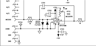
Below is a section of our megger circuit.

  • Hello Jim,

    The offset control internal circuits associated with the respective OPA111 and OPA445 input differential amplifier stages are quite similar except that the resistor values and currents through the circuits are different. Even though both datasheets indicate that a 10kΩ to 1MΩ (100k rec) potentiometer typically provides a 10 mV adjustment range that may not be enough for your application; especially, if you are trying to take out more than that out of a system. It sounds like the OPA111 has a wider adjustment range than the OPA445 and that is entirely possible.

    Since the potentiometer irrespective of the resistance value can be set to one extreme or the other than that is the setting that will provide the maximum offset adjust you will be able to achieve. And unfortunately, changing the potentiometer value to a lower one isn't going to increase the range of the OPA445.

    If it is only the voltage offset of the op amp that you are attempting to zero, would it be possible for you to use a different, more modern op amp that has very low voltage offset to start with? For example, the OPA191 has electrical performances in line with the OPA111 and a maximum room temperature of 25 uV maximum. Our modern op amps are not offered in the obsolete, round metal packages and that might be an issue for your application.

    Regards, Thomas

    Precision Amplifiers Applications Engineering

  • The meter is a qualified product, and some changes to the circuitry would require re-qualification. This is a significant expense, in both time and money, which we are trying to avoid.

    The op amp trim circuit is used to 'calibrate' the meter. The trim is used to zero out the other elements of the input circuit, not just the device input offset. I found several other devices that would work, but none of them have the input trim on the device. The OPA191 and 140 seem to be a good candidates, and could be mounted using an adapter board, but this does not address the circuit needed to calibrate the meter, unless we add other external components, with unknown consequences.

    We are in the process of accomplishing some testing to define the specific voltage/ current ranges that are needed to allow for calibration. I will post those results when they are available.

  • Hi Jim,

    Thank you for the explanation. I suspected that the OPA111 offset control was being used to null not only its voltage offset, but that of other contributors to the total error as well. That is not all that unusual for systems that employ op amps having the external offset null capability. Since the newer generation TI precision op amps have extremely low input voltage offset, the external null function is not included in their design. However, that takes away the ability to null out other system errors.

    Do let me know what you determine with regard to the voltage/current ranges needed for calibration. Maybe we can come up with some clever way to null the offsets using some other method.

    Regards, Thomas

    Precision Amplifiers Applications Engineering

  • Tom,

    I wanted to let you know that we believe we have found a solution. Some of the OPA111 circuits use the trim pins and some do not. We found that, in the circuits that do not use the trim pins, the OPA445 works just fine. On the ones that use the trim pins, there is a 500 ohm trim pot, in addition to the fixed resistors, in the feedback network. We increased the trim pot value to 1K, and we now have enough trim authority to calibrate the circuits. 

    Thank you for your help. Best regards, Jim.