Because of the Thanksgiving holiday in the U.S., TI E2E™ design support forum responses may be delayed from November 25 through December 2. Thank you for your patience.

This thread has been locked.

If you have a related question, please click the "Ask a related question" button in the top right corner. The newly created question will be automatically linked to this question.

INA121 with single polarity power supply

Other Parts Discussed in Thread: INA121, TINA-TI

Hi, I'm trying to find a way to use an INA121 with only a single voltage supply. I've created a simple Tine-TI simulation of an INA121 with a +- 5V dual supply and everything simulates exactly as I would expect. But if I try to change the supply to a single +5V and set the reference pin to 2.5V with the negative supply pin at ground, with the same sinusoidal input, I get only a dc output of +2.5 volts.I've read that the 121 is strictly dual polarity, but I've also seen references to its use with a single supply. Any help with this issue would be appreciated.

  • Hi Bob,

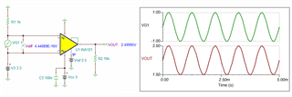
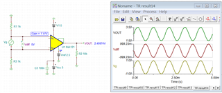
    I put together a simulation based on your description with Gain = 1V/V (did not specify). 

    Enclosed is the simulation of the above image. 

    INA121 E2E 12132021.TSC

    Please check out the Vcm of the INA121 vs. Vout. The optimum Vcm should be configured at approx. 3Vdc. 

    If you have additional questions, please let me know 

    Best,

    Raymond

  • Hi Raymond. Many thanks for the quick reply and the example! This forum continues to be a gem.

    I have to admit to being mystified by the issue of Vcm, which I assume refers to the common mode voltage. I think I understand how a differential input removes identical voltages which appear at both inputs. But this example represents the first time I have encountered insertion of a bias voltage at the voltage source (which reflects my ignorance, nothing more!). Can you explain why 3V in series with the source, and can you explain to this clueless person why a pair of resistors to ground suffices as input in the case of a dual supply (+- 5V) with ref = 2.5V, but not with a single supply? Just for fun, I introduced a matching resistor in place of the 3V bias and of got chaos in the output. So I understand why simply providing paths to ground doesn't work for a single supply setup.

    Hope some of this makes sense. Again, thanks for your quick reply.

  • Hi Bob,

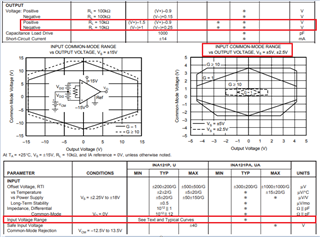
    The common-mode input voltage, Vcm, is defined as an input voltage range in which the op-amp's output will respond linearly when the input is applied to the op amp's  Vin+ and Vin- terminals. For INA121 instrumentation amplifier, these specification are listed in the datasheet as captured in the image below. The instrumentation output voltage transfer function is described as: Vout = Gains* (Vin+ - Vin-) + Vref, when it is operating linearly. 

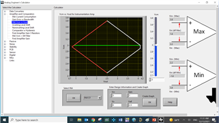
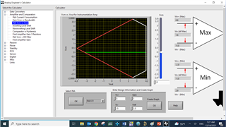
    in the case of a dual supply (+/- 5V) with ref = 0V: The Vcm and Vout relationship is defined as follows with Gain =1 V/V. The relationship is generated based on the INA121's datasheet specification as shown above.The plot below can be obtained from the TI's Analog Engineer's calculator, which the link can be found below. The tool is trying to help user to understand the Vcm and Vout relationship easier.  

    https://www.ti.com/tool/ANALOG-ENGINEER-CALC

    The simulation below is with dual supply voltages and Vref = 0V. 

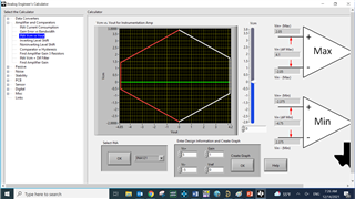
    in the case of a dual supply (+/- 5V) with ref = 2.5V, but not with a single supply? : The Vcm and Vout relationship is found in the image below. 

    The simulation below is with dual supply voltages and Vref = 2.5V. Also see the attached Tina-TI simulation. 

    INA121 E2E Gain 1 12142021.TSC

    In the case of a single supply (+5V) with ref = 2.5V:  The Vcm and Vout relationship is generated from the previous reply.

    Please keep in mind that Vout vs. Vcm relationship has to fall within the boundary of a given shape, which is determined by voltage supply rails, gains, Vref and input voltage of Vcm (shown in green line).  When a green line or Vcm is configured in the center of the given shape, Vout vs. Vcm can be maximized for a given input and output relationship.  

    If  you have additional questions, please let me know. 

    Best,

    Raymond

  • Many thanks.
    Thanks for the new response. And thank you for the link to the analyzer software. I understand better the how of biasing the input to a single-supply INA, and you've motivated me to look into how and why this happens in terms of the structure and operation of instrumentation amplifiers at a more basic level.
    Again, many thanks.
    Bob Edwards