This thread has been locked.

If you have a related question, please click the "Ask a related question" button in the top right corner. The newly created question will be automatically linked to this question.

BOOSTXL-AFE031-DF1: BOOSTXL-AFE031-DF1 + LAUNCHXL-F28379D: the same RX failed to work just in one meter apart

Part Number: BOOSTXL-AFE031-DF1
Other Parts Discussed in Thread: LAUNCHXL-F28379D, , AFE031

Dear Sir/Madam,

I am using EVM board BOOSTXL-AFE031-DF1 + LAUNCHXL-F28379D to test PLC performance through the power line AC220V/50Hz. There are 1 pair of them as TX and RX. DC15V is applied to AFE031’s PA_VS1/2. Line coupling circuit: Wurth 750510476 + 470nF + 2R5 uH + 1Mohm

To accelerate my development time, I apply the existing Packet "Permission to operate" (131.25kHz/143.75kHz SunSpec RSD signal) with the imported example code to test first.

At the same power line network, I can observe that 1 pair of TX and RX could work successfully (both RX and TX AFE031 blink blue LED) with AFE031 pin27 RX_PGA1_IN (Scope result: red signal shown; blue FFT – can see the 131kHz and 143kHz):

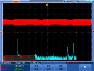
case 1: successful result at pin27

However, when I plugged the same RX one meter further in the same AC line, then RX could not work (RX not blinking blue LED but just nothing):

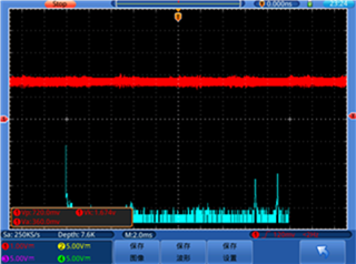
case 2: failed result at pin27

Question:

1) Is there any minimum Vrms that AFE031 pin27 RX_PGA1_IN can detect successfully after all the bandpass filter, while TX sent Vrms = 1.3V across the noisy AC power line?

2) To solve this in case 2, what do you suggest to do in TX or RX setting?


Thanks for your attention

Kelvin

  • Hi Kevin,

    1) Is there any minimum Vrms that AFE031 pin27 RX_PGA1_IN can detect successfully after all the bandpass filter, while TX sent Vrms = 1.3V across the noisy AC power line?

    The receiver has its sensitivity specification. However, I do not believe that the non-communication is your issue when you moved the receiver Xmeter away from the transmitter. Even it is 100 meter or longer, it should work properly (assume the signal losses or attenuation are kept at minimum).  

    BTW, please specify the output signal amplitude marked in the schematic below. Blue circle is the output signal transmitted by power amplifier via AFE031 IC. Red circles are incoming Rx signals received from AC powerline in your case. At the end of the reply, I will capture the AFE031's register settings for Tx/RX gain settings. 

    My guess is that the issues may be your 1meter+ away AC powerline (220Vrms, 50Hz). Here are some possibilities why it is not working. 

    1. Did you happen to use AC power strip or power conditioner module. Most of AC power adapters (especially the fancier type) have built-in with low pass filter in the AC front end of module. The Tx/Rx (131.25kHz/143.75kHz SunSpec RSD signal) signal will get attenuated, and the high modulated frequency signals are unable to get through these adapter. Please use a simply line extension to check this operation.  

    2. The 2nd possibilities are about the same power line network. The two different AC power wall sockets are required to have the same AC phase, if multi-phase AC powerlines are fed through out your building or rooms. Let us assume that there are 3-phase powerline available throughout a building or room (rare for room scenario in a vicinity), phase A vs. B or C has to go through transformer to complete a circuit when Tx/Rx transmission signals are sent via PLC application. The power transformer is likely to attenuate nearly all of incoming high frequency signals due to IR losses (sL = 2*pi*f*L)  at the transformer and block Tx/Rx signals. 

    For instance, some of ethernet communications are established through PLC application when WIFI signal is blocked across a wall, rooms or building etc.. If two connected AC sockets are on the same powerline network, the communication (Broadband PLC application) is not an issue. Otherwise, the PLC application will not work per the operating scenario. 

    Since the EVM is working in a close powerline network, this is the speculation why it is not working when it is X meter apart (powerline IR attenuation should be the minimum. Alternatively, you may increase Tx signal amplitude from 1.3Vrms or 1.8385Vpk --> the power amplifier's output should gain up to 6.5V/V or 1.84Vpk*6.5=11.9Vpk (based on the Tx transmitted amplitude figure, you should not have issues in receiving PLC packets).  

    If this is not resolving your issues, please draw a simple block diagram and upload the image over the forum or send me a setup picture.  


    If you have additional questions, please let me know. 

    Best,

    Raymond

  • Hi Kevin,

    I hope that your issues have been resolved. 

    I am going to close this inquiry. If you have additional questions, you may reopen the thread or recreate a new one via E2E forum. 

    Best,

    Raymond