This thread has been locked.

If you have a related question, please click the "Ask a related question" button in the top right corner. The newly created question will be automatically linked to this question.

OPA391: accuracy

Part Number: OPA391
Other Parts Discussed in Thread: OPA325, OPA387, OPA388, OPA369

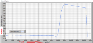
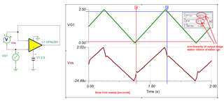
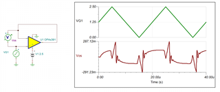
We have a problem with the OPA391DCKR. Simply used as a voltage follower, we sometimes get (scattered over several patterns) such characteristic curves: 

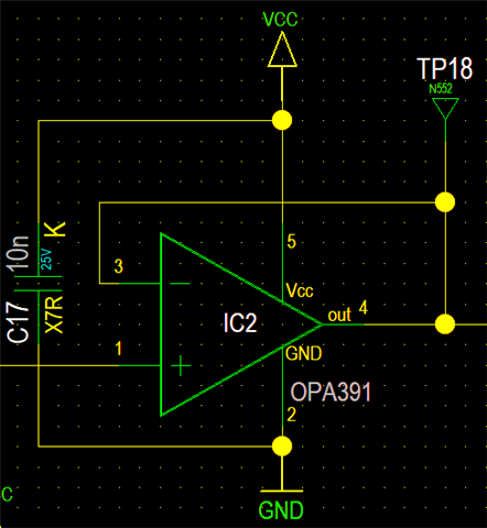
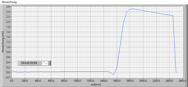
The circuit is supplied with VCC=2.5V. I have already disconnected all other connected circuit parts. (The last measuring point of the characteristic curve is inaccurate, because the voltage of the reference voltage sensor at 2.5V does not exactly match the operating voltage).

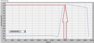
Measurements were taken with a Fluke 8846A at the output, the reference voltage transmitter is a Krohn-Hite 523. The maximum deviation of the measurement setup without the OPV is 40µV (yes, the devices are no longer freshly calibrated).

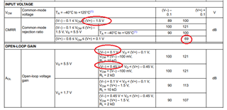
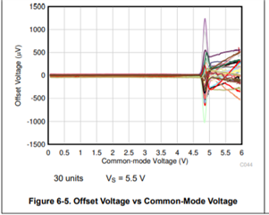
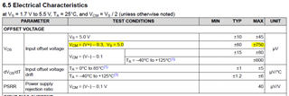
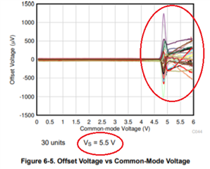
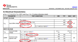
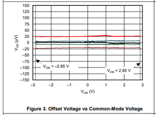
The basic course of the voltage deviation over the input voltage is outlined in the data sheet, but not to this extent. A deviation of more than 1mV is a KO criterion for us in this application. The OPV was selected because the data sheet specifies +/- 600µV over the full temperature range.

How can you explain this measurement?

  • Hanno,

    I am not clear what you show in your diagram above.  Do horizontal axis represent input common-mode voltage (Vcm) and vertical axis input voltage offset (Vos)?

    If this is the case, you may see in the OPA391 datasheet table below that the low offset voltage applies only to Vcm<(V+)-1.5V (CMRR=delta_Vcm / delta_Vos) and with Vcm close to positive rail (Vcm>1V for Vcc=2.5V) the offset may be in mV range (69dB).

  • You can see the input cross over network better in this plot - looks like about 0.7V below the supply the input stages switches over and gives much higher offset voltage - If you are using a 2.5V supply, then yes around 1.8V in the follower you show, the offset should explode. your data shows at about 0.9V below the supply, but you get the idea. 

    pretty normal for RR input without internal charge pump, if you want to get away from this, look for a "zero xover" input RRI device - those essentially have a supply charge pump to provide a higher supply to a unisex input stage to avoid this crossover effect, 

  • Hello!

    I'm the customer behind this. Yes, the x-axis is Vcm and the y-axis is Vos.

    While you are correct, the 69dB is a strong hint that the low offset only applies to Vcm>1V (with Vcc=2.5V), I am suprised about the extend. In the following table the offset at Vcc-0.3V with Vcc=5V is "only" 0.75V, so I assumed it would not be much higher than this for a lower supply voltage.

  • Hi Andreas,

    admitted, reading the offset voltage specifications is a bit tricky sometimes. I have learned that the common mode rejection ratio specification is also especially important and I read the datasheet of OPA391 in that way that the input voltage should stay 1.5V away from the positive supply voltage.

    A remedy is to give the OPA391 a gain and to put an input voltage divider at the input of OPA391 for an overall gain of 1, as we have solved this decades ago when there were no input rail to rail OPAmps available. Another remedy is to use a zero crossover OPAmp with an internal charge pump powering the input stage.

    Kai

  • According to OPA391 datasheet the LOW input offset voltage, Vos, applies only to Vcm<1V (not Vcm>1V) for Vcc=2.5V; however, you are correct that with Vcm 0.3V below positive rail (2.2V for Vcc=2.5V) Vos should still be in mV range (DC steady state) and not volts - see below. 

    Thus, there must be something else at work here and my first question would be how fast is your Vcm sweep?  If you do this slowly (in seconds), you should only see Vos variation in tens of uV for 0.1V<Vcm<1V and Vos<1mV for 1V<Vcm<2.4V;  since the linear output voltage range extend only within 100mV of either rail (see AOL conditions), for Vcm<0.1V and Vcm>2.4V on Vcc=2.5V, Vos will be in tens of mV.

    However, if your sweep is fast [in tens of us] the OPA391 cannot reject quickly enough change in the common-mode input voltage resulting in very high Vos - see below.  Additionally, the part will NOT be able to switch fast enough between two complementary input pairs (around Vcm=~1.8V for Vcc=2.5V) resulting in the horrendous non-linearity you show on your graph. Btw, the simulation below does NOT model non-linearity caused by switching between two differential pairs. 

    Having said that, if your sweep is basically DC, then yet another possible cause of the non-linearity could be resistive and/or reactive loading of the OPA391 output (you do not show any load on your schematic).

  • Hi!

    Thanks for looking deeper into my problem.

    To be very clear here: There is no "sweep". I use a precise DC voltage source (as mentioned in my first post), and hold the voltage for at least half a second before measuring. And I can definitely reproduce the values I have shown in my first diagram in a DC state without using LabView. So there is an offset voltage of up to 2.5mV (2500µV) at Vcm around 1.8V (with a unipolar supply voltage of 2.5V). And that is not a single op-amp, in my tests 7 out of 10 op-amps showed an offset of over +/- 1mV, of course always above Vcm=1V.

    And concerning your last question: As I already said above, "I have already disconnected all other connected circuit parts". Meaning the only load is the mentioned Fluke 8846A (not in high-Z-mode, but the 10MOhms should not be the problem).

  • Yes, it is possible that in the midst of transition between P and N-channel input differential pairs, around Vcm=(V+)-0.7V, the OPA391 offset may be in fact up to +/-2.5mV as shown on your graph below.

    However, there is nothing in the OPA391 datasheet that would claim less than 1mV offset at Vcm = (V+)-0.7V - see below.

    If you need a part with no Vcm transition, you should use a zero-crossover part like OPA325 - see below.

  • I think its misleading for a developer, that around the transition the offset may peak that high without any mention in the datasheet.

    But still: you marked Vos for "Vcm=(V+)-0.3V" which results in a max of 750µV. I measure 2.3mV at that point! So for me the opamp is out of spec at this specific point. Of course it is defined for Vs=5.0. But if there is such a HUGE difference for Vs=2.5V you have to mention that somewhere in the datasheet. How shall a developer work like this?

  • oh and thanks, I know the OPA325. But for reasons I won't go into detail on a public platform we can't use it here.

  • I do agree that the OPA391 maximum offset voltage for Vcm close to positive rail could be handled better by showing higher maximum offset at low supply voltage.  If you cannot use OPA325, perhaps you could use a micro-power OPA369, zero-drift OPA387, or zero-crossover, zero-drift OPA388.