A related question is a question created from another question. When the related question is created, it will be automatically linked to the original question.
If you have a related question, please click the "Ask a related question" button in the top right corner. The newly created question will be automatically linked to this question.
XTR112: How to convert 4-20mA data of XTR112 to RTD PT100 temperature?
how to convert PT100 RTD data from 4-20mA to temperature
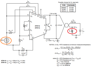
I assumed that your temperature sensing application is converted RTD resistance information to 4-20mA current loop, where the current loop is transmitted to a device on the right side as shown in the diagram below.
Let us say the RTD sensor is sensing temperature range from -20C to +150C and INA112 is converting the temperature to 4-20mA current loop on the right hand side. The temperature to current conversion is in linear relationship, where 4mA represents -20C and 20mA represents 150C as the example. The slope of the linear relationship is (20-4)mA/(150 - (-20))C = 0.094118 mA/C (4-20mA current loop vs. Temperature vs. which is linear).
To convert 4-20mA into voltage, the current has to drive a resistor, R_load as shown in red circle in the image above. Let us assume R_load = 250Ω, 4mA* 250Ω is converted to 1Vdc and 20mA*250Ω is converted to 5Vdc. In other words, 4-20mA will create 1-5V across the R_load resistor, which is also in linear relationship. R_load can be anything, as long as it meets your full scale of ADC on the data acquisition side.
There are at least three different linear relationships can be generated and plotted.
1. 4-20mA current vs. Temperature.
2. Temperature vs. Output voltage (e.g. Vout = 1-5V)
3. 4-20mA vs. Output voltage
For data acquisition purposes, Temperature vs. Output voltage relationship is more relevant, if you want to convert RTD resistance to Voltage. Per your question, you need linear relationship in graph 1 above, which is 4-20mA vs. Temperature and represented by linear equation in y = mx + b, where y is represented by 4-20mA current loop in vertical axis, m is the slope or 0.094118 mA/C as shown in the example above, x is measured in temperature, which is the x axis, b is the offset or 4mA when Temp = -20C is defined from the example above. So if the current in mA is measured or known, then Temperature can be extracted. If you know the temperature, current can be calculated within 4-20mA.
I hope that I answered your questions. If you have additional questions, please let me know.
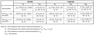
thank you very much for the answer. Another problem is I couldn't find how to convert back the 3-wire equation of RG, RLIN1, RLIN2 to R1 and R2 (min. & max. range of temperature measurement), because from the slope linear relationship you give, I need the min. & max. temperature value.
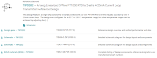
I am going to recommend to go through TIPD202 3-wire Pt1000 RTD reference design, see the link below. You can download the design information from the references below.
Since I know very little about your temperature measurement application including temperature range, RTD type (2, 3, 4 wire RTDs), performance specification and other relevant design requirements, it is difficult to answer your questions.
XTR112 IC has two constant current sources (250uA), which it is more suited for PT1000 type of RTD sensor. For RTD100 type of sensor, XTR114 may be more suited, which it generates two 100uA constant current sources. In addition, you have to consider the RTD sensor types and sensing application. You need consider and avoid possible self sensor heating error (I^2R error) when larger constant current is driving a type of RTD sensors.
I am enclosing the additional application reference, see the link below. If the application is sensing temperature in a wide range, then the linear curve fit is not suited to described the R vs. temperature curve, where RTD sensor's curve correction may be required - see the correction of the nonlinearity via hardware as suggested in the XTR112/XTR114's datasheet. You may do the similar temperature correction via MCU via 3rd order or polynominal curve fit. Please provide me some design requirements so that I am able to assist you more effectively.
The link below is the XTR112/XTR114's analog linearization method via hardware in RTD sensing application.
DIN IEC 751 standard describes Industrial Platinum Resistance Thermometer Sensors, which are manufactured everywhere over the internet. I randomly picked one of RTD manufacture for your reference. You need to select a RTD sensor of your preferred manufacturer, where you should follow the datasheet, grades (A, B, C grade etc.) , temperature performance characteristics etc.. Although these sensors are very similar in performance, you should use the manufacture recommended curve fit in order to minimize temperature measurement errors in a given application.