- Ask a related questionWhat is a related question?A related question is a question created from another question. When the related question is created, it will be automatically linked to the original question.
This thread has been locked.
If you have a related question, please click the "Ask a related question" button in the top right corner. The newly created question will be automatically linked to this question.
Hi all,
My customer would like to use this with frequencies as low as 0 to 4Hz at the input for the frequency to voltage conversion. Using the equations for Vout in Fig 18, they're trying to figure out what values of RL and RS to use. They would like to use 100K for RL and then adjust RS. But if they leave RL at 100k then RS has to be approx. 13ohms. They fear this is REALLY low and the LM331 will not like that very much, or at best it will waste a lot of current running the LM331 to ground through only 13 ohms and the resistor will get really hot.
They found a circuit where they can boost the frequency with an additional stage, but they'd rather not do that. Can you advise on what values they should set RL and RS to be given their low frequencies?
Thanks,
Lauren
Hi Lauren,
The LM331 datasheet doesn't provide information about reasonable component value ranges for the resistors such as RL, Rs and Rt. The LM331 doesn't tolerate much a wide component range if expected performances are to be obtained in actual use. For example, Rs needs to be close to 14 kilohms. That is why the Rs is most of the datasheet schematics is a 12 kilohm fixed resistor, with a 5 kilohm potentiometer. Additionally, Rt should be close to 6.81 kilohms shown in the schematics. The Pin 1 is a current output in F-to-V mode is in the 135 uA vicinity so the resistive load needs to be higher in value like 100 kilohm for a wide output voltage range.
Since the customer has preferences of the component value ranges they would like to use maybe the LM331 isn't the best choice for the application. Have a look at the LM2907/LM2917 and see if it configured as a F-to-V converter comes closer to fulfilling their requirements.
https://www.ti.com/lit/ds/symlink/lm2907-n.pdf
Regards, Thomas
Precision Amplifiers Applications Engineering
Hi Lauren,
this sort of frequency to voltage conversion cannot properly work in the Hz and sub-Hz frequency range. Remember that 0Hz means an infinite period length. Even if the LM331 would work at such low frequencies, you would suffer from huge settling times as the conversion method needs several periods to fully stabilize.
I would use a digital method. A microcontroller could easily measure the period between two consecutive edges and by this determine the frequency of input signal.
Kai
Thanks for the replies, it seems it may be better to go with the microcontroller option, but now I would like to know why the LM331 is advertised as accepting inputs as low as 1Hz if it doesn't perform to spec? That's confusing and can be misleading to the customer. Can I have further clarification? Or did I miss something - please let me know.
Thanks!
Lauren
Hi Lauren,
The datasheet does indicate that the LM331 has a Wide Range of Full Scale Frequency: 1 Hz to 100 kHz. Therefore, it is usable to 1 Hz on the low end. The original post indicated a need for a frequency down to 0 Hz, in which case the output would be zero. I think the concern that Kai had is if one attempts to apply the LM331 below 1 Hz say fractions of a Hertz, "you would suffer from huge settling times as the conversion method needs several periods to fully stabilize."
Regards, Thomas
Precision Amplifiers Applications Engineering
Ok, I understand, thanks for your reply! So if they were to do 1Hz to 4Hz input, and use the recommended values of resistors from the application schematics from the datasheet and the ones mentioned above, they should be able to have good/expected performance with the part without huge settling times?
Hi Lauren,
The LM331 datasheet in The F-to-V Converters section 9.3.1 states "In the simple circuit of Figure 18, this current is filtered in the network RL = 100 kΩ and 1 μF. The ripple will be less than 10-mV peak, but the response will be slow, with a 0.1 second time constant, and settling of 0.7 second to 0.1% accuracy." Additionally it states "Inherently, V-to-F converter response can be fast, but F-to-V response can not." The ripple filter renders a slow response. However, since the application minimum input frequency is 1 Hz, having a 1 second period, the filter timing should provide the noted 0.1 % accuracy.
Regards, Thomas
Precision Amplifiers Applications Engineering
Hi Lauren,
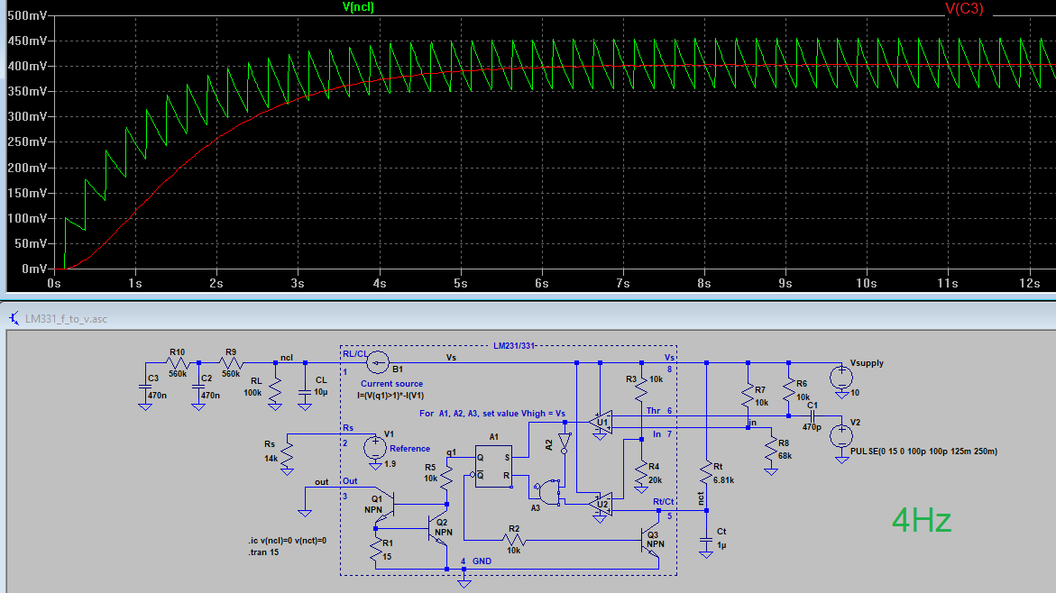
I would give this scheme a try:


(Please note that the model of LM331 shown above is not authorized by TI and does not at all include all the subtleties of the original LM331. It's only a functional model showing what ripple and settling times are to be expected with the chosen components and time constants. The model doesn't even tell whether the LM331 would work with these components and time constants. So see the simulation as a plain thought experiment.)
Kai
Hello Lauren,
Unless you have any additional questions please close this e2e inquiry.
Regards, Thomas
Precision Amplifiers Applications Engineering