This thread has been locked.

If you have a related question, please click the "Ask a related question" button in the top right corner. The newly created question will be automatically linked to this question.

LM258: LM258 Input Common Mode Range issues

Part Number: LM258

Dear TI experts,

Pls help to resolve my issues.

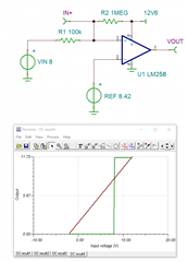
Backgroud information: I use LM258 as a comparator with signle voltage power supply, +12.6V (V-=0, V+=12.6V).  IN- connected to 8V source.

IN+ connected to a signal varying from -0.2V to +11.6V,  there is a 10MΩ resistor between IN+ and input signal.

The issues are below, for such application, is there any issue for the comparator?

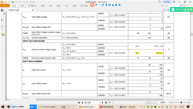
1, -0.2V < V-, pls check below datasheet, the CM voltage range, input voltage must be higher than V-. 

2, 11.6V > 12.6-2,  but input voltage must be lower than ((V+) - 2)V.

  • Hello Yu,

    The input bias current will create a voltage drop across the input resistance. At typical -20nA  the voltage would be -200mV so cross over would happen at 7.8V ; the larger the IIB, the greater the difference.

    Signal input of -0.2V to 11.6V will be fine because -0.2V is nearly zero input diode current (with 10M voltage drop, input would be about 0V anyway). 11.6V is OK because other input is 8V

    There is no hysteresis so a noisy signal input that is near threshold could result in output chatter (noise)

  • Dear Michallick, thanks for your reply. 

    I think the CM range is not applicable strictly for this comparator design, right? Because there is no negative feedback design.

    For the precise comparing of a comparator, due to the varying IB, Ib max =300nA, dV=3000mV=3V, Vc=5V ,this is not my target.

    What is your opinion for this precise issue? Change 10MΩ to 100k?The dVmax=30mV?

    Thanks.

  • Yu,

    Solutions are

    A) 100k being much better

    B) Changing to CMOS comparator (very low input current).

  • Hi Ron,

    I checked LM258A, Ibmax is only 100nA, much lower than 300nA. It is much better to replace.

    I simulated by 100k resistor, the minus voltage of IN+ Pin is lowered to -0.445V assumed the input voltage is -0.5V.

    For LM258A, dV=100nA*10M=1V, allowed to use.

    If need to keep voltage of IN+ higher than -0.3V, the minimum resistance is 4.7M, as below.

  • Hong,

    Tuning the input resistance is not a good way to allow input to be more negative voltage.

    What is the absolute maximum negative input signal that must have a correct output?

    Note that a more negative input pin voltage could create out phase reversal. (output could go high)

  • Hi Ron,

    The maximum minus value is -0.4V in front of the 10M resistor by assumption,considered all case.

    I take this value for all the simulation.

    10M resistor could keep IN+  positive input.

    2.4M could keep IN+ higher than -0.3V.

    If consider the precise comparing point and IIB, I will use 2.4M. But considering the CM voltage, it better to go 10M.

    What is your opinion?

    Thanks.

  • Hong,

    The circuit below changes output when input signal is 8V.

    Input can vary from -2V to 12V (even 30V) and have the correct output and positive IN+ voltage

    The 8.42V can be made by changing your divider resistors.  

    Does the input impedance of the comparator really need to be high?

    If yes, then make R1 1M and R2 10M, and bump up REF divider to be 8.46V