This thread has been locked.

If you have a related question, please click the "Ask a related question" button in the top right corner. The newly created question will be automatically linked to this question.

TINA-TI: What do I do to get correct behavior?

Part Number: TINA-TI
Other Parts Discussed in Thread: OPA172, TL084H, TL074H

Hi, Teams.

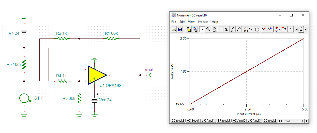
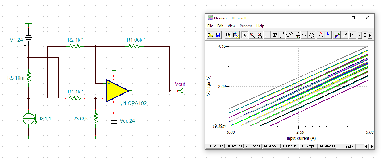
We'd like to use OPA172 in the Hi-side current sensing circuit for getting 0V-3.3V from 24V.

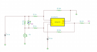
I made a schematic of the simulation refer to below the website.

High-side current sensing with discrete difference amplifier circuit | TI.com Video

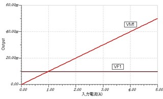
It was expected to seem work of the reference website but it was not working.

Hereby attaching the simulation circuit and its result.


HI-SIDE CURRENT.zip

  • Hello,

    This is an intentional model effect to alert users that running this op amp with input near positive rail will turn out poorly in reality and turn out nonfunctional in simulation. OPA172 is not rail to rail input although it is functional up to the positive rail.

    TL074H or TL084H would be a better choice here. Its common mode goes up to positive rail. 

  • Hi User,

    be very careful when doing high-side current measuring with a differential amplifier containing discrete resistors. The manufacturing tolerances and individual drifts of the resistors in the feedback loop in combination with the huge common mode input signal (high-side voltage !) can cause extreme measuring errors. Here the result when using ideal resistors

    and when taking +/-1% toleranced resistors:

    user_opa192.TSC

    This leads to a deviation of up to +/-26%! More, the common mode rejection of this circuit is disastrous (worse than 30dB).

    TI has specialized "current sense amplifiers" which have the four resistors sitting on the same die. So the resistors are perfectly matched and balanced. A common mode rejection of more than 120dB can easily be achieved:

    https://www.ti.com/amplifier-circuit/current-sense/products.html

    Kai

  • Hi Michallick,
    I'm sorry for my late reply.
    I had days off on the weekend.
    Thank you for your inputs.
    This schematic worked by changing Vcc to 26V from 24V!

    Sincerely,