This thread has been locked.

If you have a related question, please click the "Ask a related question" button in the top right corner. The newly created question will be automatically linked to this question.

INA333: Discrepancies in TINA simulation

Part Number: INA333
Other Parts Discussed in Thread: REF200, INA326

Hi Team,

Can you have a look at the following customer inquiry?

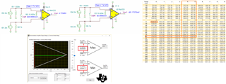
They have simulated their application in TINA and are seeing some discrepancies.

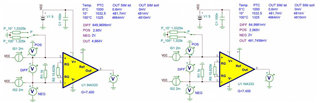
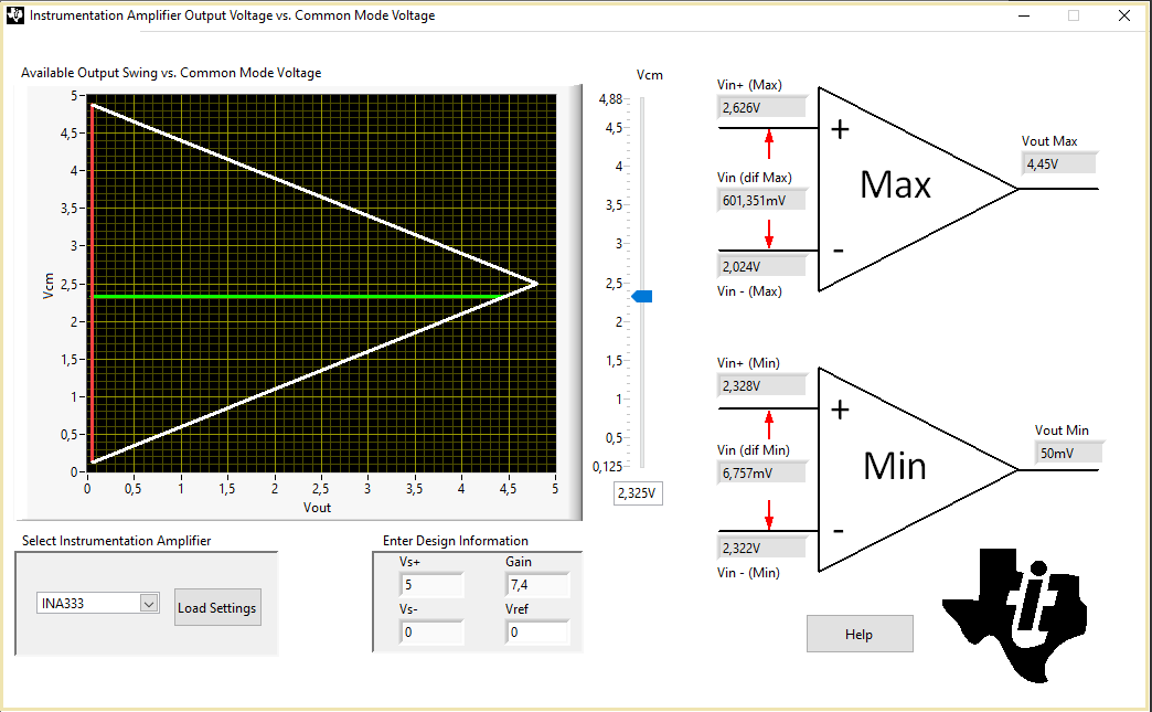
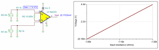
Basically, we now have a functional circuit with the INA333.
The offset voltages at the inputs are 2Vdc.
Nevertheless, the simulated results are next to the expected values.
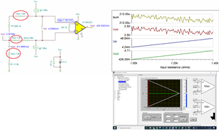
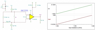
The gain factor is a low 7.4 and should give 4810mV instead of 4664mV at the output with a differential voltage of 650mV, 146mV too low.
A differential voltage of 600µV should result in 481.7mV at the output instead of 481mV, i.e. 700µV too much.
Shouldn't the amplification factor be more linear with this circuit?

Thank you,

Franz

  • Hi Franz,

    the INA333 is not capable of outputting 4.81V in this configuration:

    Kai

  • And for the lower PT1000 resistance I get this result:

    franz_ina333.TSC

    By the way, is a measuring current of 2mA not way too much for a PT1000 element? Think of the huge self-heating.

    Kai

  • Hi Franz,

    Thanks Kai for the reply! In addition to Kai's comments, here are my 2 cents. 

    1. Kai is correct that 2mA constant current may be too high. PT!000 sensor will dissipate approx. I^2R or 2mA^2*1kΩ = 4mW at 0C or 1kΩ. If we assumed that self heating coefficient approx. 0.4C/mW, then there will be additional 0.4C/mW*4mW = 1.6C minimum self heating errors in the configuration (assume low T measurement is 0C). Please check the PT1000 datasheet about the self heating coefficient. 

    Typically, approx. 100uA of constant current is used for RTD application (increase the gain of INA333). If this is the case, PT1000 will dissipate approx. 0.01mW minimum (assume low T is 0C), the self heating in PT1000 may be negligible.  

    2. As Kai pointed out, the PT1000's schematic is able to operate within the differential input range from 6.757mV to 601.351mV, see the image below. The circuit will not be operating in a linear region if the differential input voltage exceeds the above input range.   R_pt1000 = 1.325kΩ or 85C is obtained from PT1000 table below. Please check your PT1000's temperature chart (I do not recall that there is European or American sensor variations in PT1000 chart or coefficient differences. It should be based on IEC751 standard). 

    3. The simulation figure in Vos is a typical figure. The actual Vos measured at INA333's output will be different from the simulated Vos figure, which it may be better or worst than the figure specified by the datasheet. 

    If PT1000 is treated in a linear response, say INA333's Vout vs. Temp (0-100C), the linear relationship (y = ax +b) may be considered, where y is INA333's output voltage or Vout, a is the slope of Vout vs. Temp and b is the INA333's offset voltage. If the Vos (refer to output or RTO) is subtracted from Vout, (Vout -Vos) vs. Temp should be very linear between 0 < Temp < 100C (assumed the self heating errors are negligible).  

    If  you have additional questions, please let us know. 

    Best,

    Raymond

  • Hi Raymond,

    I had already downloaded the calculator, but the results look different with the same parameters.
    Accordingly, I would come to a maximum output of 4.05V, which was already 4.664V according to the simulation.

    Are we both using different states of the calculator or the Spice model ?

    Surely the current is too high for the PT1000, in other application circuits from your company the REF200 is used with two 100µA reference sources. In our current circuit with the EL8170 it is 106µV.
    If I would work with 100µA, I would get a Vcm of 116mV, but at which the INA333 would completely refuse to work.
    The challenge is that our PTC is connected to ground, I can't get it differentially connected to the INA333 and the INA333 needs a BIAS voltage at the inputs to reach the ideal Vcm of 2.5V with our single 5V.

    Best regrrds,

    Franz

  • Hi Franz,

    Are we both using different states of the calculator or the Spice model ?

    You have the latest calculator and I got the same results as you have. If the Vcm is configured differently in a circuit vs. calculator, the Vout results could be different.  

    The challenge is that our PTC is connected to ground ...

    Per your and Kai's suggestion, you may use the following circuit if PT1000 is connected to ground, but you have to alter your design. For sensing temperature range from 0C-100C, you can treat the Vout vs. Temperature as a straight line, which PT1000 RTD's nonlinearity may be ignored. 

    Enclosed is the application note for this design approach. 

    0647.slyt442.pdf

    Alternatively, you may use the following design approach. It can be 2 or 3 wire PT1000 sensor, where the simulation included the lead resistance and Vcm is configured at 2.5V to maximize the Vout swing range. 

    Enclosed is the application note for the above approach and simulation. 

    https://static5.arrow.com/pdfs/2013/11/24/3/19/23/744/txn_/manual/slau520.pdf

    INA333 3lead PT1000 01132022.TSC

    3rd option if you want to keep the existing RTD analog front end, you may use INA326 for the temperature measurement. Enclosed is the simulation and application note, and there are other RTD configurations that are prescribed in the application note. 

    INA326 2lead PT1000 01142022.TSC

    https://www.ti.com/lit/ug/tidu969/tidu969.pdf?ts=1616776511847&ref_url=https%253A%252F%252Fwww.google.com%252F

    If  you want to keep INA333 IA for the RTD design, you may implement dual supply voltage rails, where PT1000 may be connected to GND (with Vref = GND or 0V). However, you may limit your Vout swing. You may add a gain stage after INA333, you will get 0-5V output for the application. 

    There are many approaches in designing the RTD application. If you have additional questions, please let me know. 

    Best,

    Raymond

  • Hi Raymond,

    Enclosed is the application note for this design approach. 

    0647.slyt442.pdf

    Ah, I was searching for this appnote! Slight smile

    Franz, these simple analog circuits work very well. The only drawback is the calibration. Can the customer carry out the calibration in software? Or is he forced to adjust trim pots?

    Kai