Hello,
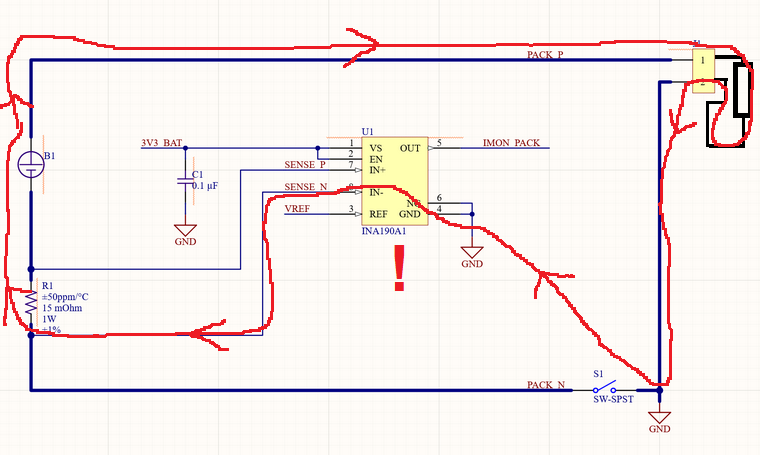
I have found a weird issue with one of our products. Please see simplified schematic. I will do my best to explain the steps to make this issue occur. We are using a INA190A1 to monitor the bi-directional current on a battery pack. The product has a low-side power switch to disconnect the battery pack from the rest of the product during shipping and transport. Here is the issue:
1.) The battery charger is connected to J1.
2.) Low side power switch S1 is closed, connecting the battery charger to the battery.
3.) Battery begins to charge. 3V3_BAT is 0 V, as the product has not turned on and started to regulate 3V3_BAT. The only thing "on" is battery which is charging.
4.) If S1 is opened and the charger disconnected, a voltage is still present across J1 (PACK_P and GND). The voltage is about 500 mV less than the battery voltage. Attaching a 0.5 A load across PACK_P and GND sinks current out of the battery, and U1 gets extremely hot in a short period of time.
5.) The only way to remove the voltage present across PACK_P and GND is to physically remove the battery from the battery pack. Inserting the battery once removed brings it back to the default condition of 0 V.
We are planning on changing this design so that U1 is on the high side of the battery, but I would like to know why this potential current path between IN- and GND exists on the INA190.
Thanks,
Alex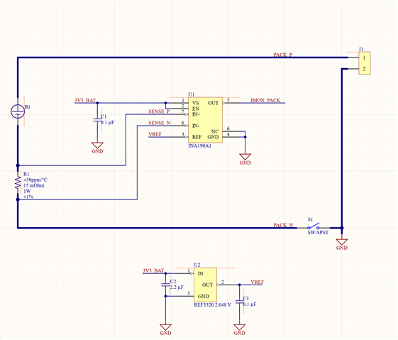

-
Ask a related question
What is a related question?A related question is a question created from another question. When the related question is created, it will be automatically linked to the original question.