This thread has been locked.

If you have a related question, please click the "Ask a related question" button in the top right corner. The newly created question will be automatically linked to this question.

INA281-Q1: a parasitic element in the input / output section

Genius 4840 points
Part Number: INA281-Q1
Other Parts Discussed in Thread: INA281

We got some questions about INA281-Q1 from customer.

We received an inquiry to know if there is a parasitic element in the input / output section of the IC internal circuit.

Since it cannot be confirmed from the block diagram in the data sheet, the customer would like to get a detailed internal circuit.

If you cannot submit it, please check the presence or absence of parasitic elements in the internal circuit input / output section.

Regards,

Kura

  • Hi Kura,

    what do you mean by "parasitic elements"?

    There's a "bias network" at the input of INA281, as shown in figure 9.1. But details on it are confidential. I don't think that TI will disclose any information on it.

    Kai

  • Hello Kura,

    Kia is correct.  Please state the root concern for requiring the circuit and I may be able to explain the behavior required for use in an application.

  • Javier-san

    Thank you for your reply.

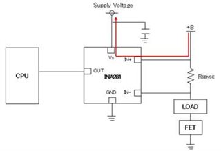
    They are considering the circuit configuration as shown in the figure below.

    At this time, they are concerned about the current wraparound of the red line.
    Is there any problem with the circuit configuration shown in the figure?
    Also, if you have any other concerns, please let us know.

    Regards,

    Kura

  • Hello Kura,

    Our current sense amplifiers are designed to not have the inputs limited by the supply.  The input bias current will depend more on the input voltage difference and not the difference between the input voltage common mode and the supply voltage.  Please see figure 5 through figure 9.  The input bias current supplies the inputs so that the voltage can be above the supply voltage.

  • Javier-san

    Thank you for your comment.

    Please give us your advise more.

    The content of the question is:

     1.Is there any problem with the presented circuit configuration?

     2.Is there any current wraparound in the red path?

     3.Is there any other concern?

    .
    Would you please advise above 3 questions from customer.

    Regards,

    Kura

  • Hello Kura,

    Below is my reply.

    1. There is no issues with that circuit.  See figure 5 in the datasheet to get the "Input Bias Current vs Common-Mode Voltage" when you have no current through the Rshunt what currents will run through the inputs.
    2. Same response as above.  The current will go to GND but will be in the µA as seen in figure 5
    3. There is no concern as these parts are meant to operate in this condition.  You can order and EVM to gain confidence in the setup.

    Please let me know if you have any other concerns.