This thread has been locked.

If you have a related question, please click the "Ask a related question" button in the top right corner. The newly created question will be automatically linked to this question.

BUF802: Spice Model error

Part Number: BUF802
Other Parts Discussed in Thread: TINA-TI,

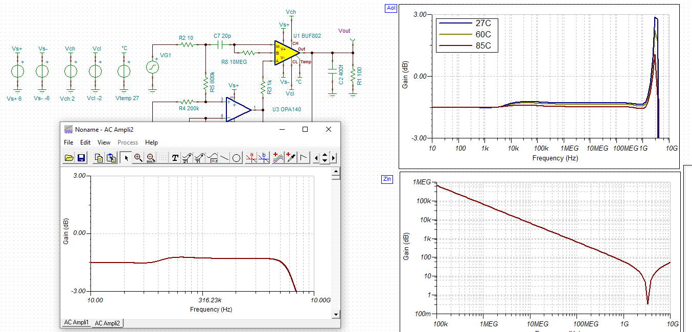
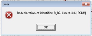
After loading the "BUF802 TINA-TI Reference Model" from the website into TINA 9, and trying to run the analysis (DC or AC) of the circuit, I get an error related to the Model

Is there an update to the Spice Model of the BUF802 circuit?

  • Hi Jean-Jaques,

    I get the same error message Scream

    I have the version: "Version 9.3.150.4 SF-TI"

    Kai

  • Hello All , can you send me the TINA file 

  • Hi Shreenidhi,

    here it comes:

    jean_buf802.TSC

    Kai

  • Deleting one of the two lines starting with "R_R2" allows ( seems) the model to work properly!

  • Hi Jean-Jaques,

    but the frequency response seems to look different:

    Kai

  • There is another problem with the model concerning the maximum output voltage.
    I have modified the schematic with
    Vch = 6V, Vcl = -6V and VG1 = 3.4V sine
    With the transient analysis the output signal is clipped at about +2.9V and -2.9V, in contradiction with  the datasheet.

  • Hi Jean-Jacques,

    At the last minute, I had added a 1G ohm dummy resistor at the input pin to help the model converge for a current input, specifically for a capacitor bootstrap application. I added it to the netlist directly as "R2", and unfortunately did not see that there was already a reference designator "R2" in the PSRR circuit. You can change 

    R_R2         MID IN+ R_NOISELESS 1E9

    to 

    R_R100         MID IN+ R_NOISELESS 1E9, or use the attached.

     BUF802_GWL.TSC

    I am updating the BUF802 model based on updated measurements I have taken using our low-parasitic third EVM revision, which should be available on ti.com next month. This model already contains some of those updates, so please disregard the previous models' validation curves. I am updating them as they become available.

    Kai,

    The original 2GHz peaking was found to be largely due to the first EVM's trace inductance, not device input inductance. The new model doesn't include that ~1nH input inductance, so its frequency response looks less resonant than the response in the embedded image.  

    Thank you for you patience as I compile my latest testing data for this new device, I assure you that the finished model will be great.

    Best regards,

    Sean