Other Parts Discussed in Thread: OPA820, , OPA684, OPA683, TLV3501, LM2596, LM2674, TLE2426, LM27762, TINA-TI, LMV7219
Due to the requirements of the application, most notably temperature and vibration, I have been unable to find suitable RF LNA or OOK demodulation packages as off-the-shelf products. Therefore I am designing a receiver specifically for this application. I encountering several problems in the design of this receiver.
Key Questions:
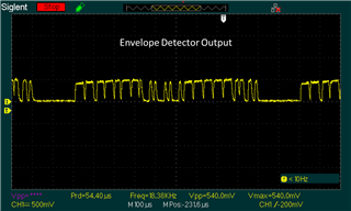
- Why the distorted output from the high Q band-pass filter?
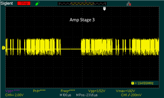
- Why does the third amplifier stage not amplify in “realistic” simulations using Boyle model?
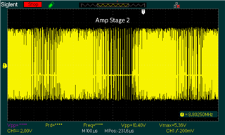
- Why do the amplifiers not manage large signals very well?
The rest of this document is an effort to give a detailed description the shortcomings of this receiver design as it relates to questions 1-3.
APPLICATION
I am building an RF receiver to receive a transmitted serial data stream. The receiver can be very close to the transmitter, which results in a very strong signal being received. The receiver must be able to demodulate a very large signal (as large as +24 dBm). The receiver can also be very far from the transmitter, which results in a very weak signal being received. The receiver must be able to demodulate a very small signal (as small as -56 dBm).
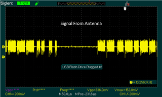
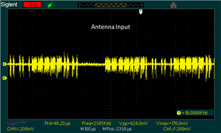
The RF transmitter is transmitting a 1.5 MHz carrier wave. The transmitter modulates the carrier wave using On-Off Keying at a frequency of 133 KHz to encode the serial data stream message. A dominant bit is transmitted as a 7.5us burst of 1.5 MHz carrier wave. A recessive bit is transmitted when the carrier wave is switched off.

RECEIVER DESIGN REQUIREMENTS
- Environment
- 125°C Maximum Operating Temperature
- Receive RF Signal From Antenna
- On-Off Keying (OOK) modulation
- Carrier Frequency = 1.5 MHz
- Message Frequency = 133 KHz
- Small Signal Amplification
- V_IN_MIN = 0.001 Vpp (-56.02 dBm)
- V_OUT_MIN = 2 Vrms (19.03 dBm)
- Total Gain Required >= 75 dBm
- Amplification Factor = ~5,500 V/V
- Large Signal Attenuation
- Max Attenuation Required >= -1.43 dBm
- AMPLIFICATION FACTOR = ~5,500 V/V
- V_IN_MAX = 10 Vpp (23.98 dBm)
- V_OUT_MAX = 3 Vrms (22.55 dBm)
- FILTER
- Isolate carrier frequency in very noisy environment
- Implement high Q factor band pass filter (Q>=10)
- DEMODULATION
- Implement envelope detector
- INPUT MODULATION = ON OFF KEYING (OOK)
- CARRIER FREQUENCY = 1.5 MHz
- MESSAGE FREQUENCY = 133 KHz
- DOMINANT BIT = SIN WAVE
- RECESSIVE BIT = NO SIN WAVE
- OUTPUT MODULATION = SERIAL DIGITAL
- DOMINANT BIT = 0 VOLT
- RECESSIVE BIT = 5 VOLT
- OUTPUT RAMP TIME <= 0.5uS
- OUTPUT FALL TIME <= 1.5 uS
RECEIVER DESIGN
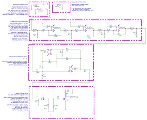
Question 1 – Why does the filter output look distorted?
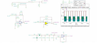
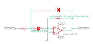
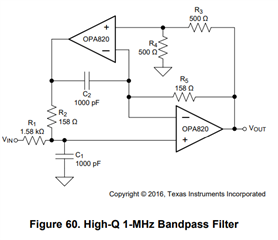
This topology is configured according to Figure 60 of the datasheet for the OPA820. The filter has been designed for a cutoff frequency of 1.5 MHz with a Q of 10 according to the design procedure described in section 10.2.1.2.1 of the OPA820’s datasheet.

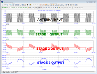
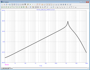
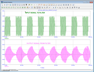
The AC response of the filter performs as expected. However, the transient response is not acceptable for the following demodulation stage. In ideal simulations, the high Q band-pass filter output “rings” when the carrier signal is removed, and “charges” when the carrier signal is applied. What do I need to do to make the output look just like the input?
Question 2 – Why don’t these opamps amplify as expected using Boyle Model?
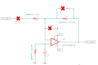
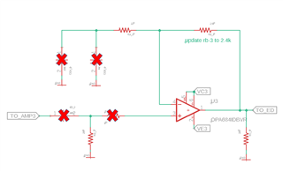
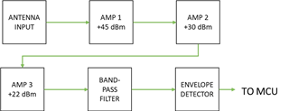
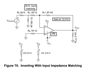
This topology is configured according to Figure 75 of the datasheet for the OPA838. The amplifier has been designed for 50Ω Impedance, and is configured in 3 stages. To reduce noise amplification, he first stage produces 50% of the total gain (45 dBm), the second produces 30% of the total gain (30 dBm), and the third produces 20% of the total gain (23 dBm). The datasheet contains recommended resistor values for gains ranging from 15 dBm to 26 dBm. As stage 1 and 2 require more than 26 dBm gain, resistor values have been derived. Care has been taken to maintain the relationship between Ri and Rf displayed in table 2 of the data sheet.

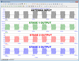
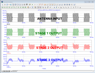
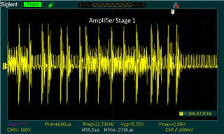
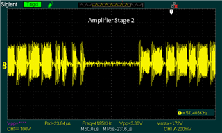
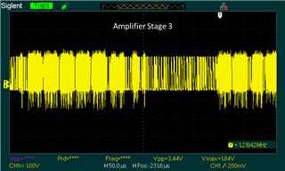
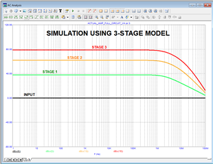
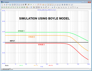
In more realistic simulations, using Boyle model for the opamps, the first amplifier stage amplifies the signal as expected. However, in the 2nd and 3rd stage, the signal isn’t amplified at all, it is actually attenuated to the point that it is weaker than the input signal. This does not occur with the more ideal models like the 3-stage model. What do I need to do to fix this issue? Is this some sort of impedance matching issue?
QUESTION 3 – Why don’t these amplifiers like larger signals?
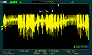
Using the ideal model for the opamps, a small signal can be amplified as expected from 1uVpp to 10uVpp. However, above 100uVpp, the amplifier does not behave as expected. It behaves as if it has been overloaded, or “jammed”. How can I fix this problem?
