This thread has been locked.

If you have a related question, please click the "Ask a related question" button in the top right corner. The newly created question will be automatically linked to this question.

OPA2343: OPA2343 simulation model downloaded from ti.com is not virtual short with single +6v power supply.

Part Number: OPA2343

As described above, my customer downloaded the opa2343 simulation model from ti.com, and then found that it's not virtual short with single +6v power supply, but it is virtual short under the practical test. And of course, the model is ok with supply voltage under 5.5v. Can you help to explain this?

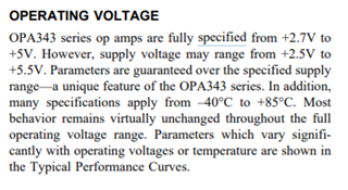
what's more, can you help me to understand the difference between the Specified Voltage Range and Operating Voltage Range showed on the datasheet.

thanks, and best regards. 

Marsh cai

  • Hi Marsh,

    and then found that it's not virtual short with single +6v power supply

    What do you mean by this?

    Kai

  • Hi Kai

    Customer uses OPA2343 simulation model on ti.com to do the simulation. When they use +5.5V/0V to power OPA2343, OPA2343 works normally. The voltages of non-inverting, and inverting inputs are same. When the OPA2343 is powered by +6V/0V, OPA2343 works abnormally. There's a obvious voltage drop between the non-inverting, and inverting inputs.

    However, when customer did the experiments with OPA2343 on the EVM with the same power supply of +6V/0V, the voltages of non-inverting, and inverting inputs are the same.

    Customer wants to know the course for this difference between the simulation model and real chip. Is this normal?

    Btw, could you help me understand the Specified Voltage Range (2.7V-5V) and Operating Voltage Range (2.5V-5.5V) in the datasheet.

    If you have any further question, please feel free to ask me.

    Thanks and BRs,

    Marsh

  • Hi Marsh,

    some models don't want that you leave the recommended operating conditions and begin to work improperly, if you do so.

    And sometimes there's even a "weird behaviour" built into the model, as a reminder, when the recommended operating conditions are violated.

    Can you post the simualtion file that makes issues?

    Kai

  • Hi Kai,

    Thanks for your reply.

    Btw, could you help me understand the Specified Voltage Range (2.7V-5V) and Operating Voltage Range (2.5V-5.5V) in the datasheet.

    Commonly, which power supply range should we use?

    Marsh

  • Hi Marsh,

    2.7V...5.0V is the supply voltage range specification you should look at when deciding what supply voltage to choose. So you can choose a supply voltage of 2.7V at the lower end and 5.0V at the upper end.

    But to allow for some manufacturing tolerance of supply voltage regulator and/or some (little) noise and/or (little) ripple on the supply voltage line, the OPAmp will still work at 2.5V and 5.5V, which is its specified "operating voltage range".

    Kai

  • Hey Marsh,

    Thanks for your interest in our device. Kai is correct, the models are only designed to function within the recommended operating conditions. They are at best models that give you many characteristics like overload recovery, Aol/Zo, short-circuit current limit (and many others), and at worst for some older devices a collection of poles and zeros that gives you Aol and meets the minimum requirements of amplifier function.

    What the models will not do is show you how the part will function in failure modes or in cases outside of the limits of the part. Even the simple models that just give Aol will give incorrect results well past the GBW of the part.

    Additionally, the answer to your specified vs operating voltage terminology can be found in the datasheet on page 8

    Best,
    Jerry 

  • Hi Jerry,

    Thanks very much for your detailed and clear explanations. 

    With your and kai's help, i totally understand the difference. 

    Thanks again, BRs,

    Marsh,