This thread has been locked.

If you have a related question, please click the "Ask a related question" button in the top right corner. The newly created question will be automatically linked to this question.

TLV3501: Tpd

Part Number: TLV3501

Hi Team,

Customer is trying to characterize the Tpd vs factors.

Customer uses triangular waveform at different freq to compare and found Tpd difference in TINA simulation vs real test. 

Before helping customer to work out a meaningful data, I want to double verify if my understanding is correct, thanks for help.

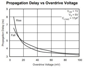
1. Tpd mainly depends on overdrive voltage btw input pins? My feeling is that it's difficult to connects existing Tpd data with a moving signal at either IN+ or IN-, overdrive vs Tpd chart is more about DC voltage vs output delay, so is there any method we can roughly determine Tpd in a triangular waveform (for example 50kHz and 5kHz) with existing chart as below?

2. CMRR can be used to calculate how much Vos error is produced based on common mode voltage being applied to input pins,  [IN(+) - IN(-)] / 2 ?

    for example if CMRR = 70dB, common mode 1V will result in 316uV offset, considering TLV350x 5V device, the working input range is small, so CMRR should be a small factor to Tpd, correct?

Thanks!

Andrew

  • 1. Draw the overdrive-vs-time curve of your signal into that chart, and see where the curves intersect.

    2. Yes. Understanding Operational Amplifier Specifications says:

    5.10 Common-Mode Rejection Ratio
    Common-mode rejection ratio, CMRR, is defined as the ratio of the differential voltage amplification to the common-mode voltage amplification, ADIF/ACOM. Ideally this ratio would be infinite with common mode voltages being totally rejected.
    The common-mode input voltage affects the bias point of the input differential pair. Because of the inherent mismatches in the input circuitry, changing the bias point changes the offset voltage, which, in turn, changes the output voltage. The real mechanism at work is ΔVOS/ΔVCOM.
    In a Texas Instrument data sheet, CMRR = ΔVCOM/ΔVOS (gives a positive number in dB).
    CMRR, as published in the data sheet, is a DC parameter. CMRR, when graphed vs. frequency, falls off as the frequency increases.
  • Hello Clemens,

    Thank you for your help on this thread, it is much appreciated :) 

    Hello Andrew,

    Thank you for your question. I agree with the information that Clemens provided. I would like to add some info for your first question.

    I will reach out to you offline and I will now close this thread.

    Best Regards,

    Joe

    Applications Engineer

    Linear Amplifiers Business Unit | Comparators Product Line (CMPS)

    All information in this correspondence and in any related correspondence is provided “as is” and “with all faults”, and is subject to TI’s Important Notice (http://www.ti.com/corp/docs/legal/important-notice.shtml)

  • Thanks a lot Clemens and Joe!