This thread has been locked.

If you have a related question, please click the "Ask a related question" button in the top right corner. The newly created question will be automatically linked to this question.

OPA228: Voltage adjustment in cyclic voltammetry circuit

Part Number: OPA228
Other Parts Discussed in Thread: OPA2197, OPA828, LMP7721

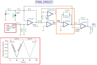
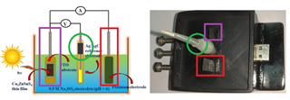
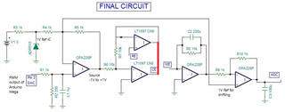
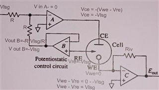
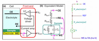
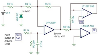
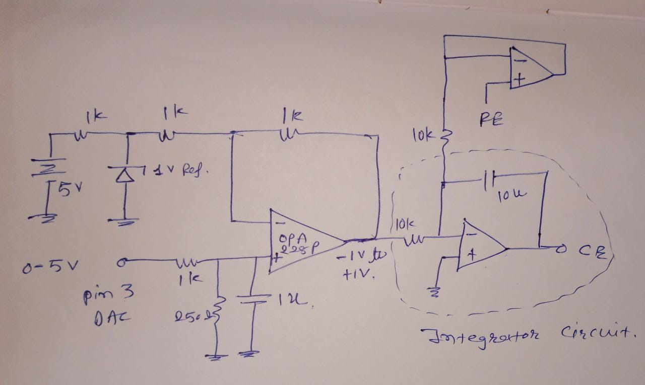
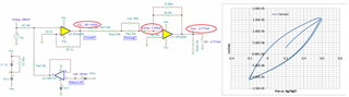
This is a circuit of cyclic voltammetry in which all three electrode i.e. WE (Working Electrode), CE(Counter Electrode) & RE (Reference Electrode) are dipped in electrolyte solution.

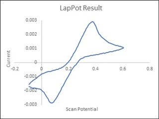
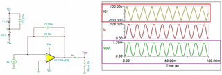
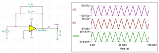
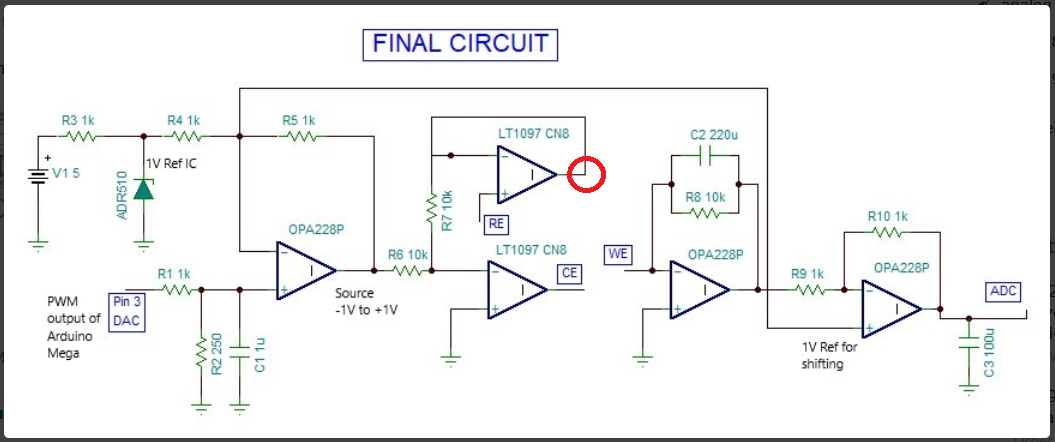
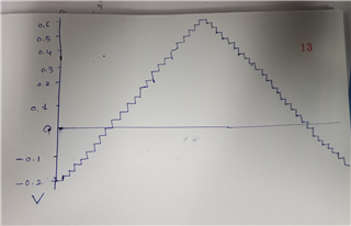
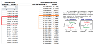
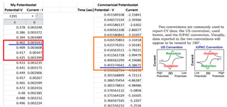
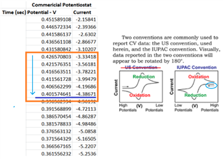
The source voltage is -1V to +1V (mentioned in circuit) but generally we are using -0.2V to +0.6V as scanning voltage. During scanning (-0.2V to +0.6V), I have measured the voltage between working electrode (WE) and reference electrode (RE) which is -0.4 to +0.8V (approx.) which should be -0.2V to +0.6V and this is happened due to electrolyte (solution resistance).

The circuit may need to improve by taking feedback from WE & RE to make it exact -0.2V to +0.6V.

I want few suggestion for circuit improvement.

  • Hello Nirav,

    We need a better understanding of your potentiostat application circuit. Please consider the following and provide explanations:

    • What supply voltages are being applied to the OPA228 and LT097 supply pins?
    • Is the circuit operating within the OPA228 common-mode voltage input range (Vcm) of (V–) + 2 V to (V+) – 2 V?
    • The OPA228 is optimized for closed-loop gains of 5 or greater. It can become unstable with gains less than 5 which appears to be what you are using.
    • The working electrode (WE) op amp is employed as a transimpedance amplifier, an I-to-V converter. That role is usually best fulfilled by a very low input current op amp, often a JFET input or CMOS input op amp. The OPA228 is a bipolar input op amp and its TA = –40°C to 85°C input bias current of ±10 nA is quite high compared to the JFET or CMOS op amp input bias currents. They are often in the picoamperes. The higher input bias current can contribute considerable error if the electrode current is small compared to it.

    Regards, Thomas

    Precision Amplifiers Applications Engineering

  • Hi,

    We previously suggested an example with the OPA2197 rail-to-rail input/output amplifier powered with ±12V supplies. The OPA2197 is unity gain stable and has low ±5pA input bias current optimal for the transimpedance for the I-V converter. The stability analysis and compensation was pending since no information was provided regarding the impedance (or the equivalent circuit) of the solution/chemical cell under test.

    Regards,

    Luis

  • Hi Nirav,

    Could you share the I vs. V curve with us in a redox reaction? I assumed that you are still using Ag/AgCl reference electrode, which it has an electrode potential about 0.197V depending on the concentration of electrolyte (saturated KCl adquous solution).  Please specify the following parameters. 

    1. scan from -0.2V to +0.6V vs. Ag/AgCl reference and what is your scan rate in mV/sec or similar units. 

    2. The potential at pin3/DAC should be triangle waveform, see the red marked rectangular. Your image is mentioned in PWM signal (are you doing staircase ramp).  

    3. I noticed that the BW of TIA is very very low, I was expected that the BW should be a minimum of 100Hz or higher. The BW should be related to the maximum scan rate of your system, e.g. 1mV-100mV/sec or others. 

    4. Please specify the redox convention. The reduction quadrant may be defined as in either current flow or electron flow (American vs. European/international convention). 

    5. Can you describe how the following measurement is made (the voltage between working electrode (WE) and reference electrode (RE) which is -0.4 to +0.8V (approx.))?

    6. What is max. rated current in your potentiostat instrument? In your CE, assume that you are using Pt wire. Please use Pt foil and increase the surface area, if you could. If you do not have Pt foil in hand, you can flatten the Pt wire and roll it into a wider surface area. Also, place the Ag/AgCl reference electrode close to WE electrode, say CE is within mm range from WE.  If Ag/AgCl have a large distance from WE in the electrolyte, you do not get an accurate potential vs. reference per the measurement (unless your electrolyte is extremely conductive). It is possible that the placement of CE may explain why you are getting weird results in step 5. 

    7. I Assumed that you are using a standard redox solution, a known concentration aqueous redox solution or electrochemical kit purchased on a market. If you formulated your own redox electrolyte, please make sure that you have recommended concentration (moles/liter) of redox species and salt concentration in the solution. To test your setup, you will need a known redox electrolyte. Once the system is working, you may do what you want. Otherwise, you are dealing with too many unknowns and do not know where the issues are. 

    8. Please send us a close image of your 3-electrode chemical cells.  

    Hope this helps. If you have additional questions, please let me know. 

    Best,

    Raymond

  • Hello Thomas Kuehl,

    What supply voltages are being applied to the OPA228 and LT097 supply pins?

    The supply voltages are +/-12V.

    Is the circuit operating within the OPA228 common-mode voltage input range (Vcm) of (V–) + 2 V to (V+) – 2 V?

    The circuit is operates within voltage range -1V to +1V.

    The OPA228 is optimized for closed-loop gains of 5 or greater. It can become unstable with gains less than 5 which appears to be what you are using.

    As the gain is less than 5 still

    its gives proper output as shown in image. 

    The working electrode (WE) op amp is employed as a transimpedance amplifier, an I-to-V converter. That role is usually best fulfilled by a very low input current op amp, often a JFET input or CMOS input op amp. The OPA228 is a bipolar input op amp and its TA = –40°C to 85°C input bias current of ±10 nA is quite high compared to the JFET or CMOS op amp input bias currents. They are often in the picoamperes. The higher input bias current can contribute considerable error if the electrode current is small compared to it.

    Your suggestion is valuable. Which JFET or CMOS op amp with very low input bias current is suggestable. 

    Thank you, 

    Nirav

  • Hello Kai Klaas,

    Yes it is related with earlier thread.

    Thanks,

    Nirav

  • Hello Luis Chioye,

    OPA2197 is useful op-amp in my application for I-V converter. 

    I have two question.

    1. Is OPA2197 is suggestable for control amplifier in given application? If not, which is ideal op amp for that?

    2. Reference electrode need to connect with op amp with highest input impedance so can I use OPA2197 for that?

    Thank you,

    Nirav

  • Hello Raymond,

    Could you share the I vs. V curve with us in a redox reaction? I assumed that you are still using Ag/AgCl reference electrode, which it has an electrode potential about 0.197V depending on the concentration of electrolyte (saturated KCl adquous solution). 

    The I vs. V curve is given below

    1. scan from -0.2V to +0.6V vs. Ag/AgCl reference and what is your scan rate in mV/sec or similar units. 

    Scan Rate is 50mV/Sec.

    2. The potential at pin3/DAC should be triangle waveform, see the red marked rectangular. Your image is mentioned in PWM signal (are you doing staircase ramp).

    I am using arduino board and pin 3 is pwm pin. It gives 0 to 5V by pwm output. As per the scan rate, the output voltage is increased like triangle wave like 0V to +5V and +5V to 0V.

    3. I noticed that the BW of TIA is very very low, I was expected that the BW should be a minimum of 100Hz or higher. The BW should be related to the maximum scan rate of your system, e.g. 1mV-100mV/sec or others

    I have used all OPA228P op amp which has which has wide bandwidth, as per datasheet it is 33MHz, 10 V/us.

    4. Please specify the redox convention. The reduction quadrant may be defined as in either current flow or electron flow (American vs. European/international convention). 

    The redox convention is European(Standard convention), not American.

    5. Can you describe how the following measurement is made (the voltage between working electrode (WE) and reference electrode (RE) which is -0.4 to +0.8V (approx.))?

    It measurement is made by digital multimeter (the voltage between working electrode (WE) and reference electrode (RE) which is -0.4 to +0.8V (approx.))compare to pin 3 output voltage through op-amp i.e. (-0.2V to 0.6V).

    The both should be same to same. 

    6. What is max. rated current in your potentiostat instrument? In your CE, assume that you are using Pt wire. Please use Pt foil and increase the surface area, if you could. If you do not have Pt foil in hand, you can flatten the Pt wire and roll it into a wider surface area. Also, place the Ag/AgCl reference electrode close to WE electrode, say CE is within mm range from WE.  If Ag/AgCl have a large distance from WE in the electrolyte, you do not get an accurate potential vs. reference per the measurement (unless your electrolyte is extremely conductive). It is possible that the placement of CE may explain why you are getting weird results in step 5. 

    The max rated current is +/- 8mA. In CE, we are using 10mm x 50mm Pt foil.

    The RE & WE is placed very near to each other. The electrolyte may be resistive solution. If it is, then how can we resolve the issue of electrolyte resistance  using electronics circuit.

    7. I Assumed that you are using a standard redox solution, a known concentration aqueous redox solution or electrochemical kit purchased on a market. If you formulated your own redox electrolyte, please make sure that you have recommended concentration (moles/liter) of redox species and salt concentration in the solution. To test your setup, you will need a known redox electrolyte. Once the system is working, you may do what you want. Otherwise, you are dealing with too many unknowns and do not know where the issues are.

    We are formulating the own redox electrolyte but the concentration is good enough and it is tested by standard commercial potentiostat.

    8. Please send us a close image of your 3-electrode chemical cells.  

  • Hi Nirav,

    I don't understand your schematic. From my understanding of cyclic voltammetry, by the help of "counter electrode" the potential of the "reference electrode" is held exactly on the same potential as the potential of the "working electrode". But if you apply a "source" voltage of +1V, e.g., the lower LT1097, after having closed the feedback loop, will have its -input at 0V, which will result in a potential of the "reference electrode" of -1V, while the "working electrode" is still 0V. So, as the "reference electrode" and the "working electrode" are not sitting on the same potential, this makes no sense to me.

    Kai

  • Hi Nirav,

    Let me comment on the 3-electrode setup first. 

    I am not able to see how the internal 3-electrodes are configured. Typically the WE has to be parallel with CE and REF electrode should be positioned closer to WE electrode and on a side of WE electrode (not directly in front of WE electrode to block the ion flows under redox reaction). The CE and  WE electrodes should be face to face to maximize the ionic charge transfer between two electrodes (itwo plates in your case). 

    In 3-electrode chemical cell, CE is sourcing the required current for a given applied potential between WE and REF electrode. The applied potential from -0.2V to +0.6V are referenced to REF electrode.  When chemical reaction are taken place at WE electrode, electrons are produced (source or sink in current at WE depending on the applied potential to REF). The current to voltage conversion is done via TIA circuit.  

    I simulated your WE electrode circuit with ±100uA sawtooth input at 100Hz, here is the result. The circuit is NOT converting the input current to voltage due to limited BW that is 200uf capacitor in parallel with 10kΩ. OPA828 has very high BW, but circuit 's BW is reduced by the dominated pole set by 200uf capacitor in the circuit below. 

    If you want to reduce the BW of the OPA828, you may place a smaller capacitor value. The dominated pole in this TIA circuit is set at approx. 8kHz and the TIA's output can convert the current to voltage via a transfer function Output_Voltage = -I_in * 10kΩ = -100uA*10kΩ , which is close to ±1Vp per the sawtooth input. 

    OPA828 I2V E2E 02102022.TSC

    Enclosed is TIA application note for your reference. The app note is tailored for photodiode application, but the principle is the same. 

    https://www.ti.com/lit/ug/tidu535/tidu535.pdf?ts=1644495472571&ref_url=https%253A%252F%252Fwww.google.com%252F

    We are formulating the own redox electrolyte but the concentration is good enough and it is tested by standard commercial potentiostat.

    I vs. V redox plot looks normal, but I am not sure if the measured current on the vertical axis is correct. Please perform the following experiments since you have an access to a standard commercial potentiostat instrument. 

    1. Obtain I vs. V plot with respect to Ag/AgCl REF from -0.2V to +0.6V at a scan rate of 50mV/sec. Technically, you have it already, but do it anyway and compare the results in step 2.  

    2.  Obtain I vs. V plot with respect to the same setup in step 1 and compare the redox current axis in vertical axis. In fact, overlap two plots on top of each other on in MS Excel graph tool, and you will see what I am talking about. You should have the identical results if the configuration is identical.  Please let me the results. 

    There are other things that have issues in the circuits. Let us perform the above experiments first and we can guide you through the rest to improve the circuit. 

    There is one more thing you can verify if your potentiostat is working correctly. 

    Please short or combine CE/REF leads or terminals together, say apply 0.1V with respect to ground at CE/REF terminals. Connect a 100Ω (1/4W) resistor between WE and CE/REF terminals (you basically connect CE/REF to GND wiht 100Ω load, which is a low voltage power supply). You should measure 0.1Vdc from CE/REF terminal to GND, and the current that go through the resistor should be 0.1V/100Ω = 1mA  (check with DMM) and ADC should measure 1mA*10kΩ = 1Vdc (from I-to-V converter). 

    Best,

    Raymond

  • Hi Nirav,

    can you comment my doubts?

    Kai

  • Hi Kai Klaas69,

    Please find the attached circuit for your kind reference.

    You can find that Vlsg is a source voltage then potential difference between working electrode and reference electrode should be Vwe - Vre = Vlsg.

    But practically, due to electrolyte resistance, potential difference between working electrode and reference electrode is vary little bit from Vlsg.


  • Hi Nirav,

    I hope that your potentiostat unit is working. 

    Your 3-electrode chemical cell block diagram is good. I would like to add that the WE electrode is modeled as a current source and the current is sourced or sinked via CE electrode, and WE electrode's potential is referenced to RE, but the RE's potential is canceled out, when WE "looks back" at CE and RE electrodes (Ic current are bidirectional). 

    You mentioned that you are using international redox convention (IUPAC), which means electrons go into the WE electrode, reduction is taken place. This is equivalent to say that the current is flowing out of WE electrode, which means the Negative potential is measured at TIA converter --> negative x-axis direction represents reduction quadrant;  and Positive potential measured at TIA's output on x-axis represents oxidation quadrant. 

    I am enclosing an application report on pH electrode, where our LMP7721 op amp is used. As you may aware, RE electrode does not involve in sourcing or sinking voltage or current (ideally) in the 3-eletrode chemical configuration, and RE is a high impedance device and the chemical setup should not be disturbed the RE potential (half cell reaction). LMP7721's Ib current is in fA range and its chemical potential shall not "load it down" the RE electrode in the electrochemical setup. 

    If you;d like to improve the setup, I would use LMP7721 or other low fA range precision op amps. Ib in nA range is a bit high for the application.   

    https://www.ti.com/lit/an/snoa529a/snoa529a.pdf?ts=1644969071985&ref_url=https%253A%252F%252Fwww.google.com%252F

    Please let us know if your 3-electrode electrochemical setup gives an accurate measurement in your application. 

    Best,

    Raymond

  • Hi Nirav,

    thanks for the clarification.

    During scanning (-0.2V to +0.6V), I have measured the voltage between working electrode (WE) and reference electrode (RE) which is -0.4 to +0.8V (approx.) which should be -0.2V to +0.6V and this is happened due to electrolyte (solution resistance).

    You should not measure directly at the reference electrode (RE) but at the buffered RE voltage. See the red circle:

    Don't forget to insert a suited isolation resistor, because digital volt meters can show a huge input capacitance which can destabilize the LT1097.

    Keep also in mind, that C2 and especially C3 might destabilize the OPA228!

    Kai

  • Hello Kai,

    This is fine but I want understand that how to overcome the electrolyte resistance due to which iR drops happen. 

    I think the quote given below is due to electrolyte resistance.

    During scanning (-0.2V to +0.6V), I have measured the voltage between working electrode (WE) and reference electrode (RE) which is -0.4 to +0.8V (approx.) which should be -0.2V to +0.6V and this is happened due to electrolyte (solution resistance

    I want to overcome the given issue. For example, if I provide the Vlsg range (-0.2V to +0.6V), Vwe-Vre should get (-0.2V to +0.6V).

  • Hello Raymond,

    I hope that your potentiostat unit is working

    Yes it is working fine.

    If you;d like to improve the setup, I would use LMP7721 or other low fA range precision op amps. Ib in nA range is a bit high for the application. 

    I have both available i.e. OPA228P and LMP7721. I can use any from it.

    Please let us know if your 3-electrode electrochemical setup gives an accurate measurement in your application. 

    Yes, It gives good result but still the redox peaks are broaden. In my application, the difference between both peak should be 0.169V but actually it is more than that.

  • Hello Raymond,

    I simulated your WE electrode circuit with ±100uA sawtooth input at 100Hz, here is the result. The circuit is NOT converting the input current to voltage due to limited BW that is 200uf capacitor in parallel with 10kΩ. OPA828 has very high BW, but circuit 's BW is reduced by the dominated pole set by 200uf capacitor in the circuit below. 

    Sorry to say that the value of R8 is just 98 ohms instead of 10k. By mistake, it is shown 10k.

    Even if the same issue exist with 98 ohms then which value of capacitor is ideal for this application?

    I vs. V redox plot looks normal, but I am not sure if the measured current on the vertical axis is correct. Please perform the following experiments since you have an access to a standard commercial potentiostat instrument. 

    I have compare the both plots and found that my circuit plot is more broader than commercial potentiostat instrument.

  • The impedance of volt meter could cause an error. So please carry out the measurement at the red circle.

    Kai

  • Hi Nirav,

    Sorry to say that the value of R8 is just 98 ohms instead of 10k. By mistake, it is shown 10k.

    Your TIA, I2V converter is not configuring properly. It has very low gains where Vout = -R8 * I_we, and the current is likely in uA range, may be close to a couple of mA range depending on the surface area of WE electrode. 

    Yes, It gives good result but still the redox peaks are broaden. In my application, the difference between both peak should be 0.169V but actually it is more than that.

    With 98Ω||200uf, you only have BW at approx. 7Hz range. That is why you have seen a very broad redox peaks (sluggish dynamic redox response) when you are performing ramp from -0.2V to +0.6V vs. RE. Near DC signal, the I2V may work correctly (except the Vout's gain is so low). And your buffer stage follows TIA has Gain of 1V/V as well. Please specify the voltage of power rails for these op amps. 

    For instance: If your op amp's supply rail is 5Vdc and ground as an example, your maximum 3-electrode's current is 8mA, your TIA gain should use approx. 5V/8mA = 625Ω resistor (500-600Ω range, if you provide some voltage overhead margin per the setup). 

    Can you send me the IV plots in excel, your setup vs. commercial cyclic voltammogram? Please send me the raw data from both devices. 

    I want to overcome the given issue. For example, if I provide the Vlsg range (-0.2V to +0.6V), Vwe-Vre should get (-0.2V to +0.6V).

    The following CE output should be summing point of RE and applied CE potential. It is not setting up correctly. V_CE potential = (V_RE + V_OPA228)/2. where V_OPA228 should be scanning from -0.2V to +0.6V at ±50mV/sec. As I indicated previously, V_OPA228's potential has to be a saw tooth. If your input is square wave, then you need an integrator to convert it to triangular wave. Can you show me the waveform measured at CE point?

    Kai is absolute correct. You will need high impedance bench grade multimeter to measure the potential between WE and RE. The impedance should be >10GΩ or higher to measure the potential accurately, like electrometer. Regular DMM won't measure the potential interface between WE and RE accurately. 

    If you have additional questions, please let me know. 

    Best,

    Raymond 

  • Raw Data - LapPot Vs Commercial Potentiostat.xlsx

    Hello Raymond,

    Please find the raw data of my potentiostat and commercial potentiostat in excel. 

    Please specify the voltage of power rails for these op amps. 

    The power is +/- 12V.

    Kai is absolute correct. You will need high impedance bench grade multimeter to measure the potential between WE and RE. The impedance should be >10GΩ or higher to measure the potential accurately, like electrometer. Regular DMM won't measure the potential interface between WE and RE accurately.

    I dont have high impedance bench grade multimeter but DMM can measure potential between WE & RE (although, it is not so accurate).

    The following CE output should be summing point of RE and applied CE potential. It is not setting up correctly. V_CE potential = (V_RE + V_OPA228)/2. where V_OPA228 should be scanning from -0.2V to +0.6V at ±50mV/sec. As I indicated previously, V_OPA228's potential has to be a saw tooth. If your input is square wave, then you need an integrator to convert it to triangular wave. Can you show me the waveform measured at CE point?

    Pin 3 DAC will provide 0V to 5V (PWM) output at (+) terminal of OPA228P and 1V reference is apply to (-) terminal of OPA228P so that OPA output voltage will be -1V to +1V range as per Pin 3 DAC voltage.

     From -1V to +1V range, I can use -0.2V to +0.6V for potential scanning purpose. 

    The waveform is look like this.

    Thanks,

    Nirav

  • Hi Nirav,

    Please find the raw data of my potentiostat and commercial potentiostat in excel. 

    I took a look at your raw data for comparison. I assumed that you are using the identical 3-electrode chemical cells. Here are what I see:

    1. commercial is using IUPAC redox convention, and you are using American redox convention. 

    2. Two plots look similar, but they are not the same (the scanning voltage range is backward based on the data). 

    3. If you are using the identical electrochemical cell, the redox currents have to be identical. If I vs. V are measured from different cells, you have to normalize the current by area, then you are able to compare the results. As it is currently, they are two different I vs. V curves (mainly due to comments in 1). 

     From -1V to +1V range, I can use -0.2V to +0.6V for potential scanning purpose. 

    I have used various grade potentiostats from very high end and low end grade, and none of them is using the staircase scanning method. I think that you need to build a integrator circuit and convert the scanning signal to triangular input. And it is easy to do. Here are my reasons. 

    when an instrument is specify a ramp, say ±50mV/sec, this is a continuous signal as a function time. From -0.2V to 0.6V at ±50mV/sec scanning rate, the time is very precise, which is 0.8V/50mV/sec = 16 secs. I am fairly sure that your instrument is not limited to 50mV/sec, it can be 100mV/sec or higher.

    Your instrument has approx. 8mV/step in the voltage step. If you look at the commercial grade one, the voltage delta is 200uV/step at the same 50mV/sec (40X difference in ramp time). I just do not want to find it out later on what are the limitation of staircase voltage ramp may be in potentiostat application. 

    I can assist you more once these issues are resolved. 

    Best,

    Raymond

  • commercial is using IUPAC redox convention, and you are using American redox convention. 

    No, I am also using IUPAC redox convention, please refer other raw data also.

    If you are using the identical electrochemical cell, the redox currents have to be identical. If I vs. V are measured from different cells, you have to normalize the current by area, then you are able to compare the results. As it is currently, they are two different I vs. V curves (mainly due to comments in 1). 

    Yes, I have used same electrochemical cell.

    I have used various grade potentiostats from very high end and low end grade, and none of them is using the staircase scanning method. I think that you need to build a integrator circuit and convert the scanning signal to triangular input. And it is easy to do. Here are my reasons. 

    So, should I put the Integrator circuit as per below given?

    I am fairly sure that your instrument is not limited to 50mV/sec, it can be 100mV/sec or higher.

    Yes, it is true, my instrument has many higher scan rate but how scan rate is related to triangular wave form?

    Thanks,

    Regards,

    Nirav

  • Hi Nirav,

    No, I am also using IUPAC redox convention, please refer other raw data also.

    If the commercial unit has configured for IUPAC convention, at approx. 0.4016V vs. Ag/AgCl, the current is -4.38671mA. In your potentiostat, the same redox potential is applied at 0.402V vs. Ag/AgCl, the current has to be negative. However, the measured current is 0.003543mA (I assumed that this is the unit). Thus the redox convention is different between the two units. 

    In  addition, the redox current should have the same current amplitude and current flow direction, especially you are using the same 3-electrodechemical cell to perform the comparison. 

    Yes, it is true, my instrument has many higher scan rate but how scan rate is related to triangular wave form?

    The redox reaction is electrochemical reaction, and it is defined as continuous redox reaction in electrolyte (this is different from electronic interface). When you are applying a step function, say staircase small signals, can you claim that the stimulus input signal at a chemical interface is same as continuous triangular waveform? The electrochemical interface reactions are complex enough, I do not believe that you want to introduce this variable into the chemical redox reaction. Furthermore, every one else is scanning in triangular waveform for an I vs. V measurement. 

    Let me try to simulate the I vs. V circuit in Tina, and post it to you by tomorrow. 

    Best,

    Raymond 

  • Hi Nirav,

    Let us revisit the sign of WE's current afterward. Let us get the simulation resolved first. Previously, I did not pay attention of the scanning direction of triangular wave, so two data can not be compared directly (they are not the same in redox activity). However, the current magnitude is incorrect and the direction of current flow at WE is incorrect as well. The buildup potentiostat is doing something different from the commercial grade unit. We can figure it out later. 

    Enclosed is a potentiostat simulation in Tina. I used a "dummy" electrochemical cell, since I did not find a good pspice double layer model (so I make up one). 

    Anyway, I plotted out the Ice2we vs. (Vce or Vwe vs. Ag/AgCl) after I simulated the circuit and exported the time domain plot in Excel, see the attached file. 

    Attached are the Tina simulation and Excel file. 

    OPA828 Potentiostat 02222022.TSC

    Potentiostat I vs V 02232022A.xlsx

    If you have additional questions, please let me know. 

    Best,

    Raymond

  • Hello, 

    I am not getting exactly your point with regards to my previous post.

    The plot shown in attached file is different. I am not getting your point.

    Regards,

    Nirav

  • Hi Nirav,

    Can you be specific? I can explain if you can tell me the point you are referring to. 

    I am going to take a guess what you may not be clear. 

    Think of 3-electrochemical cell as a complex resistor (mainly RC and some L (insignificant for your purposes). If the unit is measured in one system vs. a different potentiostat, the result has to be identical. In this case, the result is I vs. V curve, which it has to be identical, especially you are using the same electrochemical cell.

    The applied potential vs. Ag/AgCl has to be the identical; redox peak positions have to identical; and redox current amplitudes have to be identical, if all the controlled parameters are the same.  

    In your commercial potentiostat, the potential vs. Ag/AgCL is scanned from higher to lower potential (from right to left as marked in IUPAC convention). Based on the reduced potential vs. Ag/AgCl, the potentiostat is performing reduction, where electrons are inserting into the WE electrode. In other words, current direction is flowing out of the WE electrode. 

    With the current flow scenario, the TIA's output should measure negative voltage and the current calculation via TIA transfer function should be I = - Vout/Rf, where Rf is the TIA's feedback resistor. Please check with your instrumentation manual and it should be stated somewhere in the user guide.  

    Please let me know if you have additional questions. 

    Best,

    Raymond