This thread has been locked.

If you have a related question, please click the "Ask a related question" button in the top right corner. The newly created question will be automatically linked to this question.

Noise with DRV103 driving medium load

Other Parts Discussed in Thread: DRV103

I am currently trying to drive a Hydraulic solienoid pressure regulation valve with the TI DRV103 PWM Low-Side Driver. The hydraulic pressure regulation valve is from Sun Hydraulics and the specifications are located here: http://www.sunhydraulics.com/cmsnet/Parts.aspx?ModelCode=770-212&CatModelID=9963&Lang_ID=1

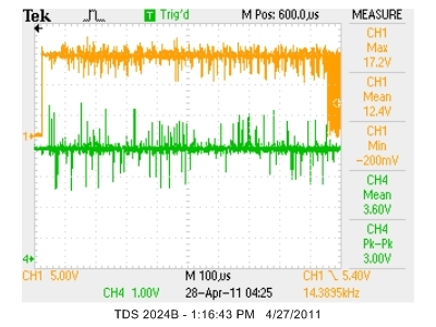
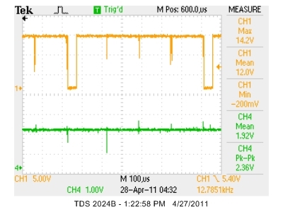
The DRV103 appears to work perfectly with a high impedance load (100kohm resistor) which is run at 12V DC PWM @ 500Hz. However, when I hook the DRV103 up to the hydraulic valve (which has a smaller impedance at the load), the output does not work (see the Oscilliscope captures below). A bad noise occurs on the output and the PWM does not function as it did with the larger load. I have verified that the same issue occurs when driving an 8ohm Resistor using the DRV103 and therefore is not caused by just the hydraulic valve.

It appears that the noise occurs when the current becomes substantial. Now the DRV103 is supposed to supply 3A of power and we are not using more than 1.5A at most with the valve or the resistor.

Things I have tried:

-running the DRV103 @ 5000Hz

-putting 22uF capacitor at supply pin to ground


Any input or help with this issue would be greatly appreciated.


Here is how I have the circuit hooked up to the DRV103H (V3 is a 12V line off of a Computer Power supply which can supply 25A on the rail it is using).

The Pres_sig_0 is a current output (0-20mA) line that goes to the R2 and R1 as a divider.

Scopes of the output (CH1, pin 5) and the duty cycle adjust (CH4, Pin 1)
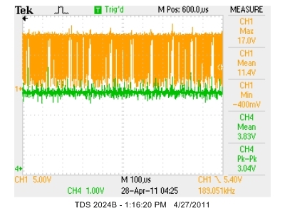
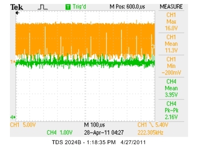
Load with the Duty Cycle increased (note the noise on the duty cycle line [pin1] and the output PWM [pin 5])
 

  • Justin,

    You've provided excellent information in your posting--schematic, info on the load, scope shots, and details on what you've tried. Thanks!

    You refer to putting a 22uF cap on the power supply pin. The IC needs some bypass capacitor. We show 1uF which is a minimum value for light loads. I suggest that you leave the 22uF cap connected.

    Your schematic does not show a flyback diode connected between pins 5 and 6 (see figure 1 of the data sheet). Maybe you thought that the surge protection diode in the valve performed this function. The internal surge protector has a high breakdown voltage in both directions and will not fulfill the function of the flyback diode. It needs to be a fast recovery type as noted in figure 1. We've seen problems when attempting to use common rectifier diodes.

    I realize that you have tried operation with a resistive load and still experienced problems. While the flyback diode is less important with a resistive load, you still might have problems without it. Also, if you have driven the valve without a flyback diode, it is possible that you have damaged the IC. Have you tried another IC?

    Another possible source of problem is the duty cycle control pin. It appears that you are creating proper control voltage here but there is a lot of noise on this pin. This could be a cause of the problem or it may be a result of the problem--I'm not sure. Try connected a 100pF capacitor from pin 1 to ground. See figure 6 and the comments above it relating to this topic.

    I hope this helps.

    Regards, Bruce

  • Bruce,

    Thank you for your quick response! I do have a flyback diode on the board (on a different part of the schematic that I didn't include); however it is just a 1N4004 rectifying diode. I will try changing that out with a faster flyback diode. Do you happen to recommend anything in particular for a flyback diode in this circumstance? Only one of the Schottky diodes listed in Figure 1 are listed on Mouser and that one is on backorder.

    I will also attempt putting the 100pF capacitor from pin 1 to ground.

    I am hoping that the issue stems from the use of a basic rectifying diode and that the use of a Schottky diode will help. I would also appreciate any other ideas that you may have that may help with the issue.

    Regards,

    Justin

  • Justin,

    Most any Schottky diode with a 2A or greater rating should be okay. Until then, it's worth trying the 100pF capacitor with the resistive load. Don't try the valve again until you get a proper diode. A significant change in the output waveform with the capacitor present may indicate that there is a noise issue on that pin.

    If the 100pF capacitor does not produce better results with the resistive load, try using a fixed resistor to program the duty cycle. Use an appropriate value from Table III for 50% duty cycle according to your programmed frequency. I'm confident that the current transmitter can be used to control the duty cycle but this is just a diagnostic step.

    Regards, Bruce