This thread has been locked.

If you have a related question, please click the "Ask a related question" button in the top right corner. The newly created question will be automatically linked to this question.

OPA858: Power supply decoupling

Part Number: OPA858

In the support response titled "OPA858: Ac coupled OPA858 non-inverting amplifier shows instable behavior", there is a recommendation to add a 20 ohm resistor to the +V power supply pin. Our design has bipolar power supplies with a -V and a +V power plane. We are adding 20 ohm resistors on both the +V and -V supply inputs. Should the Thermal Pad be connected to the -V plane or the -V pin? There question arises because of the 20 ohm resistor between the two.

Thank you for the help! 

  • Hi David,

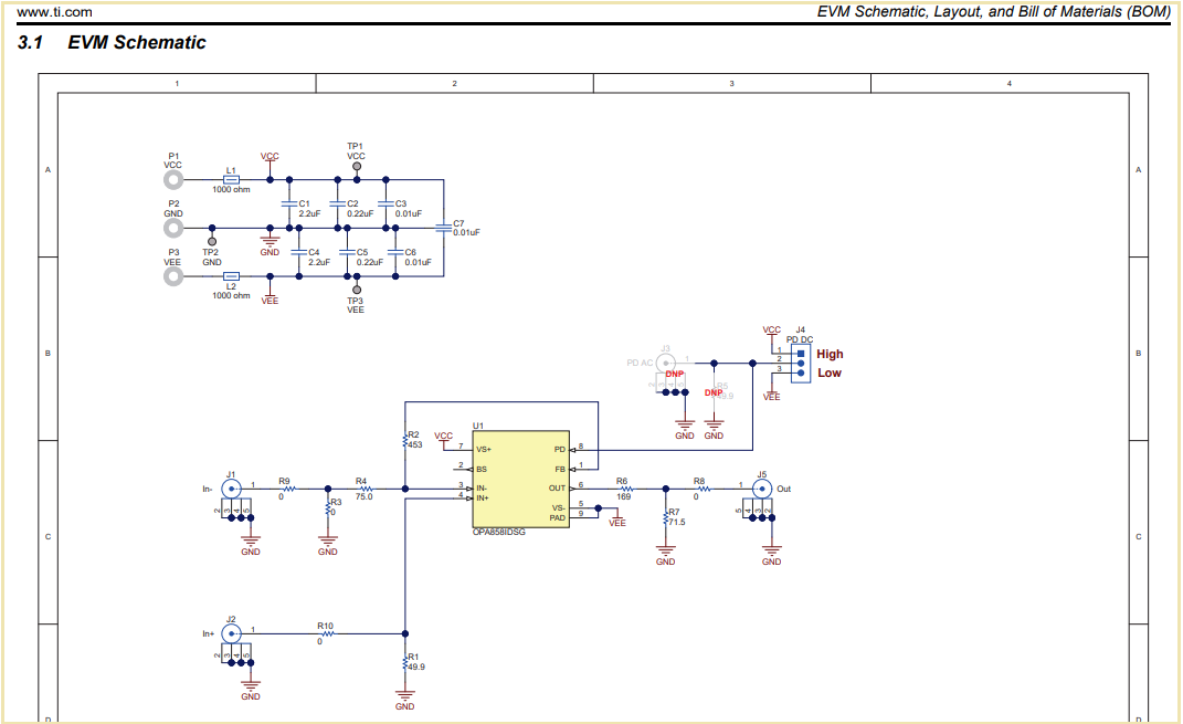
    I would do it as shown in the EVM:

    I would make a direct connection between the VS- pin of OPA858 and its pad. Or by other words, I would isolate the pad from the negative power plane.

    By the way, I think the 20R resistor in question was meant to be installed in series to the IN+ input (non-inverting input) of OPA858, not in series to the power supply pin.

    Kai

  • Kai,

    Thanks for the guidance. I confused the 20 ohm resistors with the following statement in the support response  ...

    "2. As being a 5.5GHz OPAmp you need to consequently apply HF design practises. This especially means to use supply voltage filtering by the help of series resistances or ferrite beads. Apply this for each single OPAmp and each single supply voltage. Put the series resistors and/or ferrite beads closest to the decoupling caps which themselves should sit closest to the supply pins of OPAmps. This alone could already do the trick and prevent oscillations.

    By the way, I always use PI filters for this purpose. When doing so there's no need for an extra power supply plane."

    We will connect the thermal pad directly to the VS- pin. The power pins are filtered with a PI ... C-R-C with R = 20 ohms. Also, we added a series 20 ohm resistor on the Output and the IN+ pin. (Our application is a non-inverting amplifier.)

    Thanks again!

  • Happy to help Relaxed