Other Parts Discussed in Thread: OPA858,
Hello,
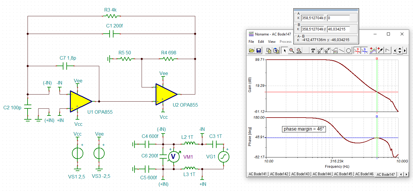
I am trying to design an amplifier to measure the time response of a photodetector (50pF detector capacitance). I'm trying to achieve bandwidth close to 500MHz with considerable (several KOhms) gain.
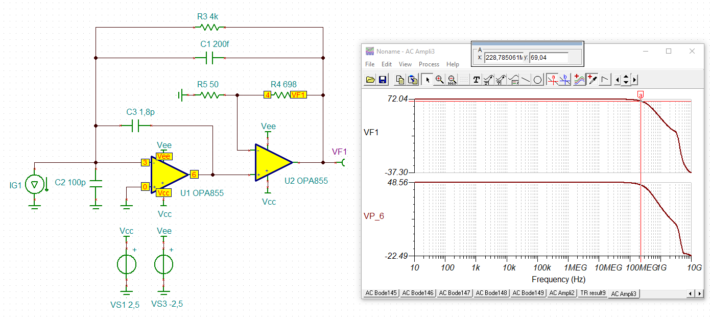
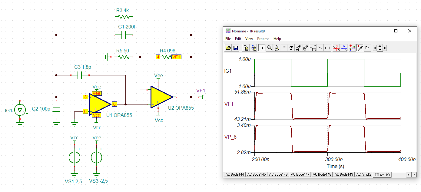
With a composite loop including OPA855 and OPA858 simulations looked promising.
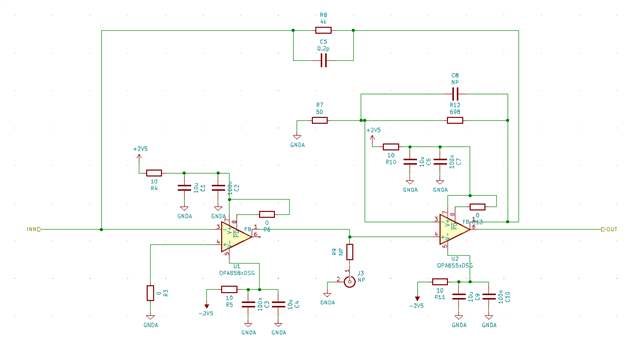
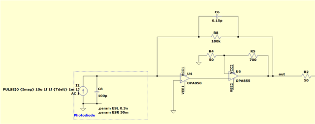
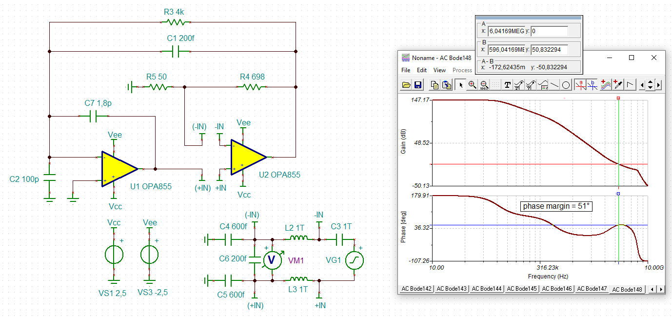
Below is my original circuit snapshot with 4K gain achieving almost 500MHz bandwidth. I know this is on the edge of stability and expected to have some tweaking in the lab. However after following mods, the circuit keeps oscillating;
1. Increased RFB to 100K
2. Increased Cd to 100pF (0603 COG)
3. Various values for CFB ranging from 0-0.3pF
4. Added NP0 supply decoupling (few nanoFarads)
(added a snapshot of the simulation circuit)
Due to not having this kind of HF tools, I'm simply measuring the output with an oscilloscope.
The last hypothesis I had was the ESL of the input capacitor. Therefore I changed the package from 0603 to 0402 (0,6nH to 0.3nH). However it doesn't seem to solve the issue.
Based on TI experience, would it be even possible to get the circuit to work up to this high frequency or is there a fundamental limit of device/package parasitic?
Thanks in advance!
Regards,
Sven